6-53
3-2. ADJUSTMENT POINTS WHEN MAJOR
PARTS ARE REPLACED
1. When drum is replaced:
“Tape Path Position Adjustment” of mechanical section adjustment
“PB RF frequency response characteristics adjustment” of the video
section adjustment
“Switching position adjustment” of the servo section adjustment
3-3. POWER SUPPLY SYSTEM ADJUSTMENT
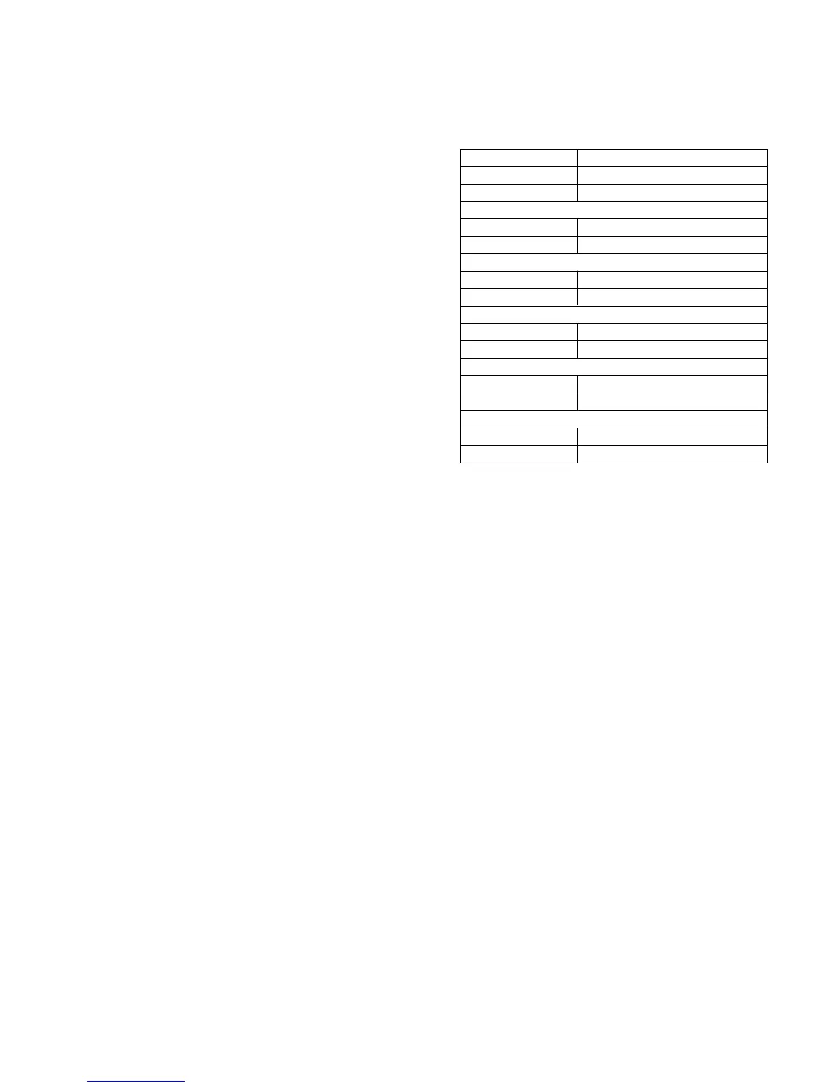
1. Power supply voltage check (VC-188 board)
Mode Camera record
Subject Any subject
Measuring Equipment Digital voltmeter
MT5V check
Measuring Point CN301 pin #º
Specification Value 5.0 ± 0.15Vdc
DIG 3V check
Measuring Point CN301 pin @£
Specification Value 3.16 ± 0.1Vdc
AU 3 V check
Measuring Point CN501 pin 5
Specification Value 3.18 ± 0.1Vdc
EVF 5V check (camera mode)
Measuring Point CN301 pin #∞#§
Specification Value 4.85 ± 0.15Vdc
EVF15 V check
Measuring Point CN301 pin #¢
Specification Value 14.95 ± 0.4Vdc