6-24
16. White balance check
Subject White pattern standard picture frame
Filter Color temperature correction filter
C14 ND filter 1.0 and 0.3
Measurement Point VIDEO output terminal
(Terminated in 75Ω)
Measuring Instrument Vectorscope
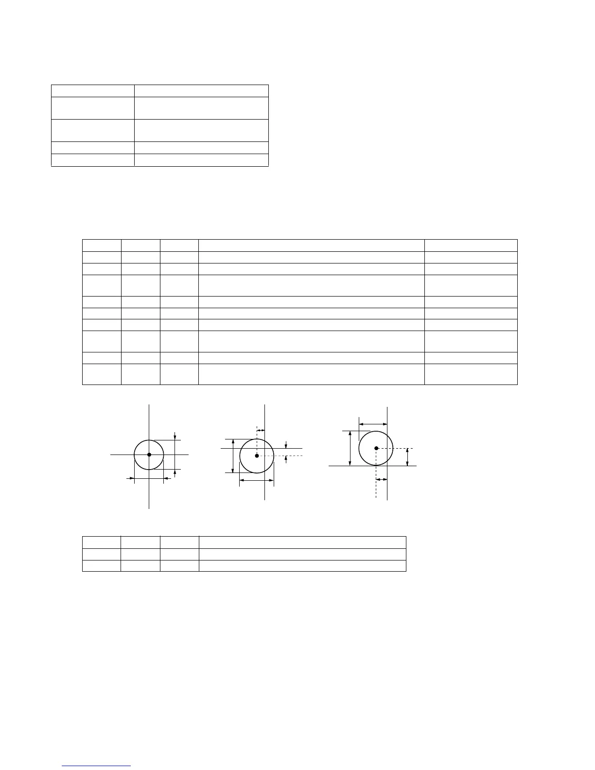
Specification Value Fig. 6-1-10. A ~ C
Note 1 : Confirm that the “Camera-shaking” correction to OFF.
(EXCEPT TRV14E MODEL)
Note 2 : Confirm that the “Digital Zoom” is turned OFF.
(EXCEPT TRV14E MODEL)
Check procedure:
Processing after Adjustments:
2mm
2mm
B-Y
R-Y
R-Y
B-Y
3mm
0.5mm
0.5mm
3mm
3mm
3mm
B-Y
R-Y
0.5mm
1.0mm
1.5mm
Ø3mm less
Ø3mm less
Ø2mm less
Fig. 6-1-10 (a) Fig. 6-1-10 (b) Fig. 6-1-10 (c)
Order Page Address Data Procedure Condition
1 Check that the lens is not covered by either filter.
2 6 01 0F After setting the data, press the PAUSE button.
3 Check that the white luminance point is located within the circle Without filter.
shown in Fig. 6-1-10 (a).
4 6 01 00 After setting the data, press the PAUSE button.
5 6 01 23 After setting the data, press the PAUSE button.
6 Put the C14 filter on the lens.
7 Check that the white luminance point is located within the circle C14 filter
shown in Fig. 6-1-10 (b).
8 Remove the C14 filter and put ND filter 1.3 (1.0+0.3) on the lens.
9 Check that the white luminance point is located within the circle ND Filter 1.3
shown in Fig. 6-1-10 (c).
Order Page Address Data Procedure
1 6 01 00 After setting the data, press the PAUSE button.
2 6 00 00 After setting the data, press the PAUSE button. (End)