6-28
19. COLOR ELECTRONIC VIEWFINDER
SYSTEM ADJUSTMENTS
[Adjustment connector]
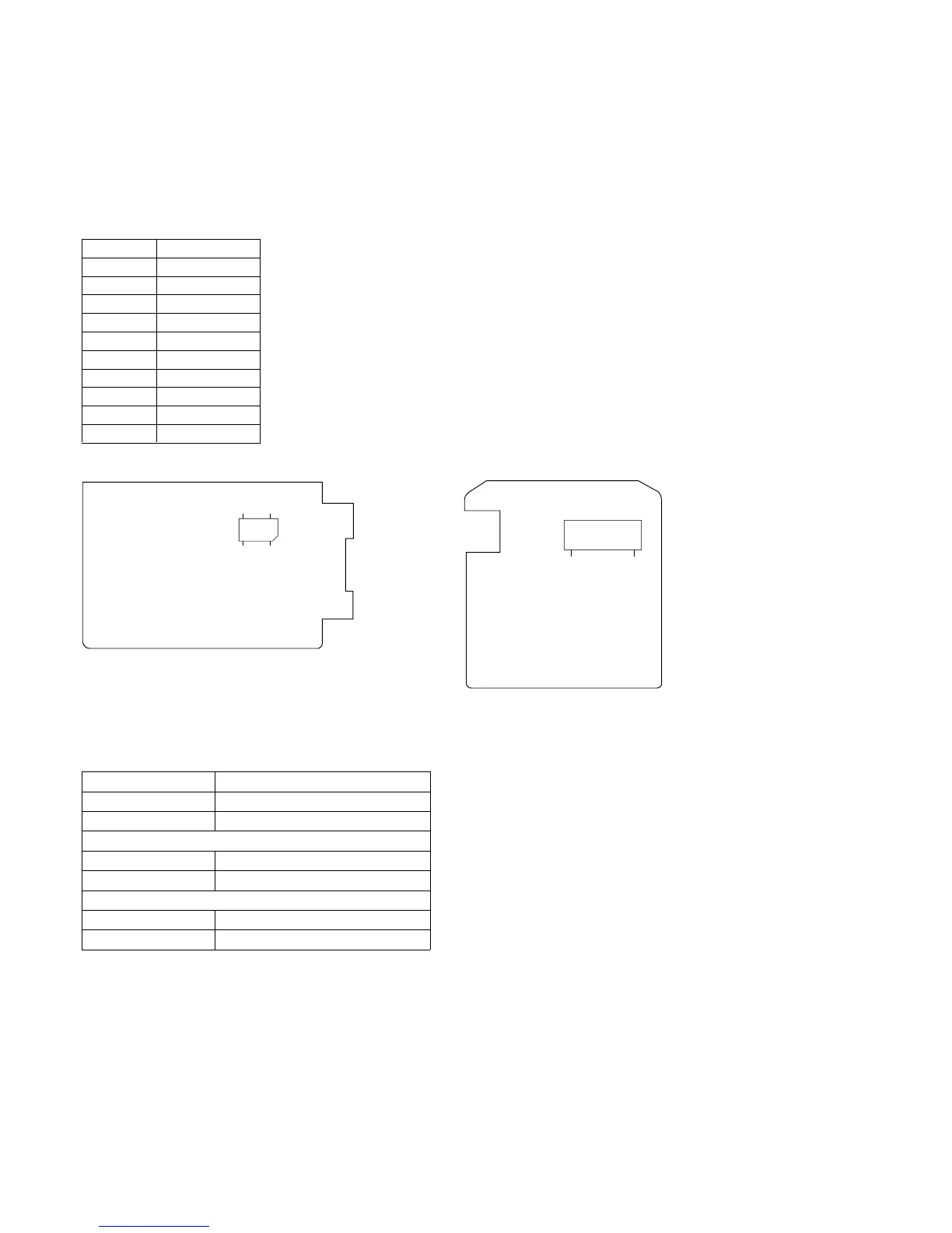
The viewfinder adjustment points have gathered to CN702 of the
VF-110 board. Connect the measuring equipment to CN702 via
the jig (J-6082-192-A). The table below shows the pin numbers
and the signal names of CN702.
19-1. Power supply voltage check (VF-109 board)
Mode Camera record
Subject Any subject
Measuring Equipment Digital voltmeter
EVF 5V check
Measuring Point CN851 pin 5
Specification Value 4.65 ± 0.05Vdc
EVF15 V check
Measuring Point CN851 pin 7
Specification Value 15.0 ± 0.05Vdc
Pin No.
1
2
3
4
5
6
7
8
9
10
Signal Name
LC COM
EVF GND
G OUT
13.5V
N.C.
12V
R OUT
B OUT
SLYT
PCO
VF-110 BOARD (SIDE A) VF-109 BOARD (SIDE A)
Fig. 6-1-13
CN851
10
1
CN702
10
2
9
1
Preparation:
Because this machine does not have VIDEO INPUT connector,
playback the alignment tape and use the playback signal for
adjustment.
Alignment tape :
WR5-5CSP : PAL
(Parts code : 8-967-995-47)
WR5-5NSP : NTSC
(Parts code : 8-967-995-42)