2-8
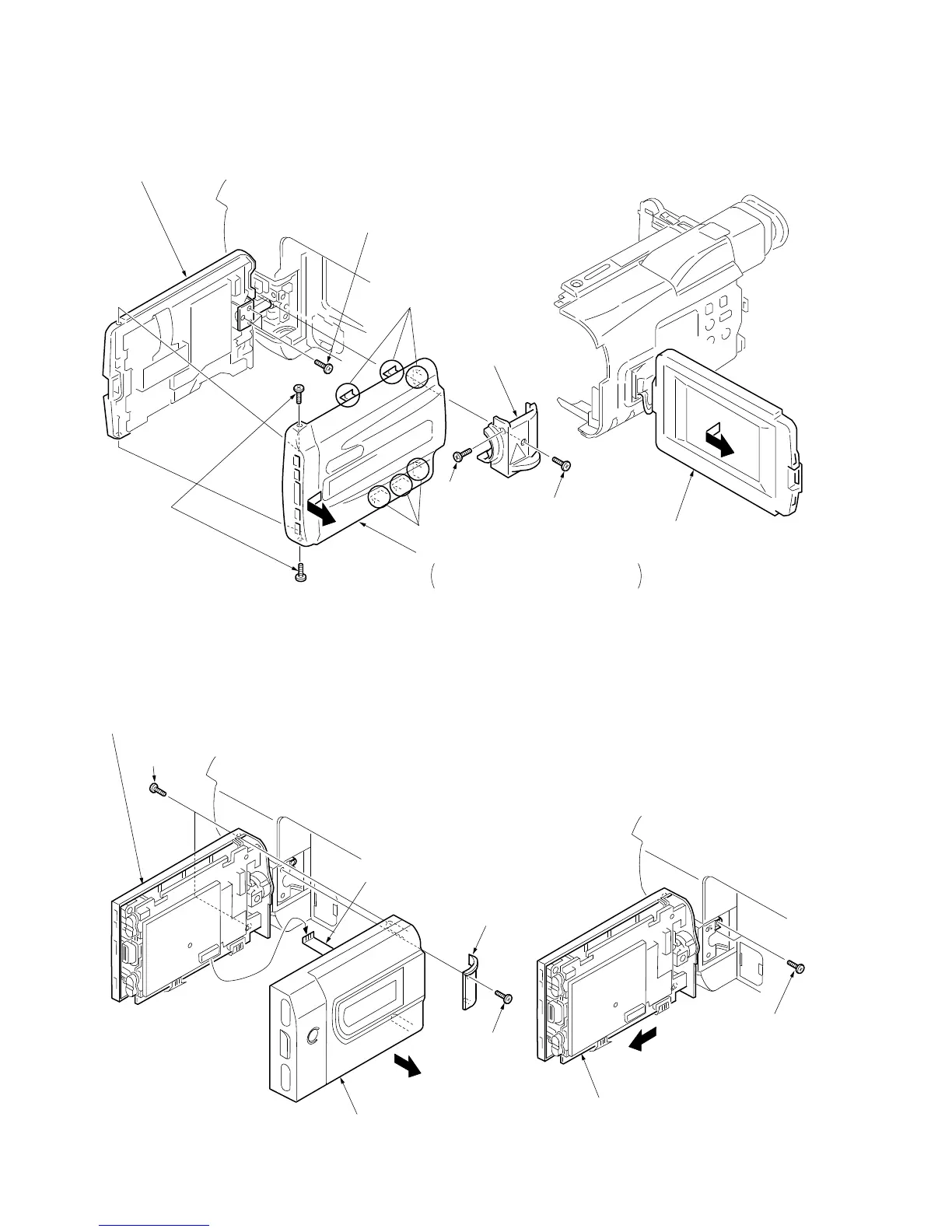
2-10(1). REMOVAL OF P CABINET AND LCD ASSEMBLY
(EXCEPT TRV14E/TRV24E MODEL)
2-10(2). REMOVAL OF P CABINET AND LCD ASSEMBLY
(TRV14E/TRV24E MODEL)
1
Move the LCD assembly
in the direction shown.
7
Screws (M2
×
3)
5
Screws
(M2
×
4)
Claws
Claws
6
P cabinet (C) assembly
Remove it in the direction of the arrow
while taking care of the claws.
4
Hinge cover (C)
2
Screw (M2
×
4)
8
Remove the LCD assembly
in the direction of the arrow.
3
Screw (M2
×
4)
1
Move the LCD assembly
in the direction shown.
3
Hinge cover (lower)
2
Screw (M2
×
4)
8
Remove the LCD assembly
in the direction of the arrow.
4
Screws
(B2
×
5)
6
Flexible
5
P cabinet (C) assembly
7
Screw
(M2
×
4)