6-29
19-2. EVR initial data input
Mode Stop
Signal Any video signal
Adjustment page F
Input procedure:
19-3. PCO adjustment (VF-110 board)
Purpose : To make the TG frequency constant
(amplitude).
Adjustment error : VF picture will lose sync when error is large.
Mode VTR stop
Signal No signal
Measurement Point VF-110 board CN702 pin !º (PCO)
Measuring Equipment Oscilloscope (DC range)
Adjustment Page F
Adjustment Address D2
Specification Value A=1.80 ± 0.05V
Adjustment procedure:
Order Page Address Data Procedure
1 6 00 01 Set the data.
2CCA0
CD AE (75)
CE 95 (50)
CF 7A
D0 6A
D1 70
F D2 90 After setting the data, press the PAUSE button.
D3 40
D4 7A
D5 7A
D6 70
D7 05
3 6 00 00 Set the data.
Order Page Address Data Procedure
1 6 00 01 Set the data. (Preparation)
2 Check the GND level on an oscilloscope in DC mode.
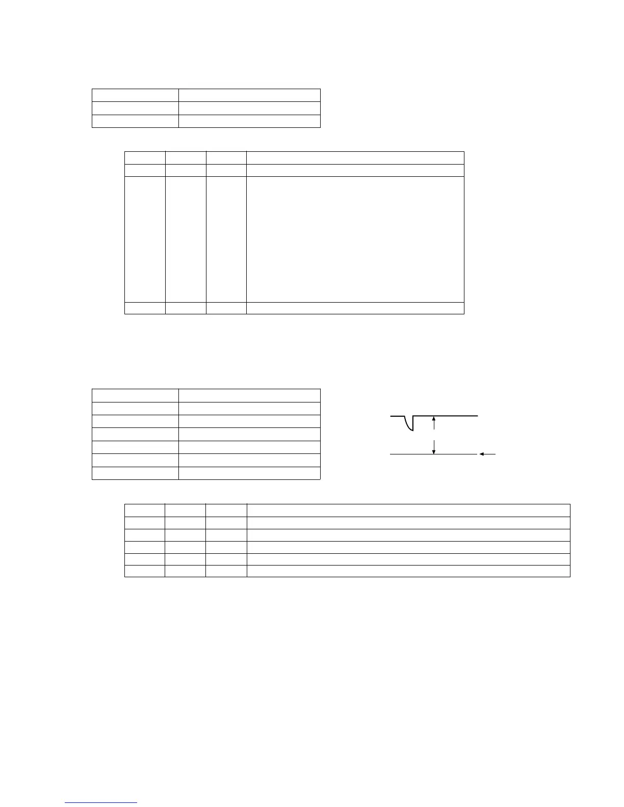
3 F D2 Change the data until the PCO voltage (A) becomes the specification value.
4 Press the PAUSE button.
5 6 00 00 Set the data. (End)
No mark : NTSC/PAL
( ) : PAL
GND level
(0Vdc)
A
PCO