6-66
3-8. YD OUT LEVEL ADJUSTMENT
Purpose : Minimizes the residual chroma component of
Y comb filter output signal.
Adjustment error : Chroma flicker at video out (pin jack) of VTR
overall characteristics. Color variations also
significant.
Mode Playback
Signal Alignment tape : Normal mode
WR5-5CSP (PAL)
WR5-5NSP (NTSC)
Measurement Point IC201 pin @¢ or CN102 pin 5
Measuring Instrument Oscilloscope
Adjustment Page F
Adjustment Address 3C
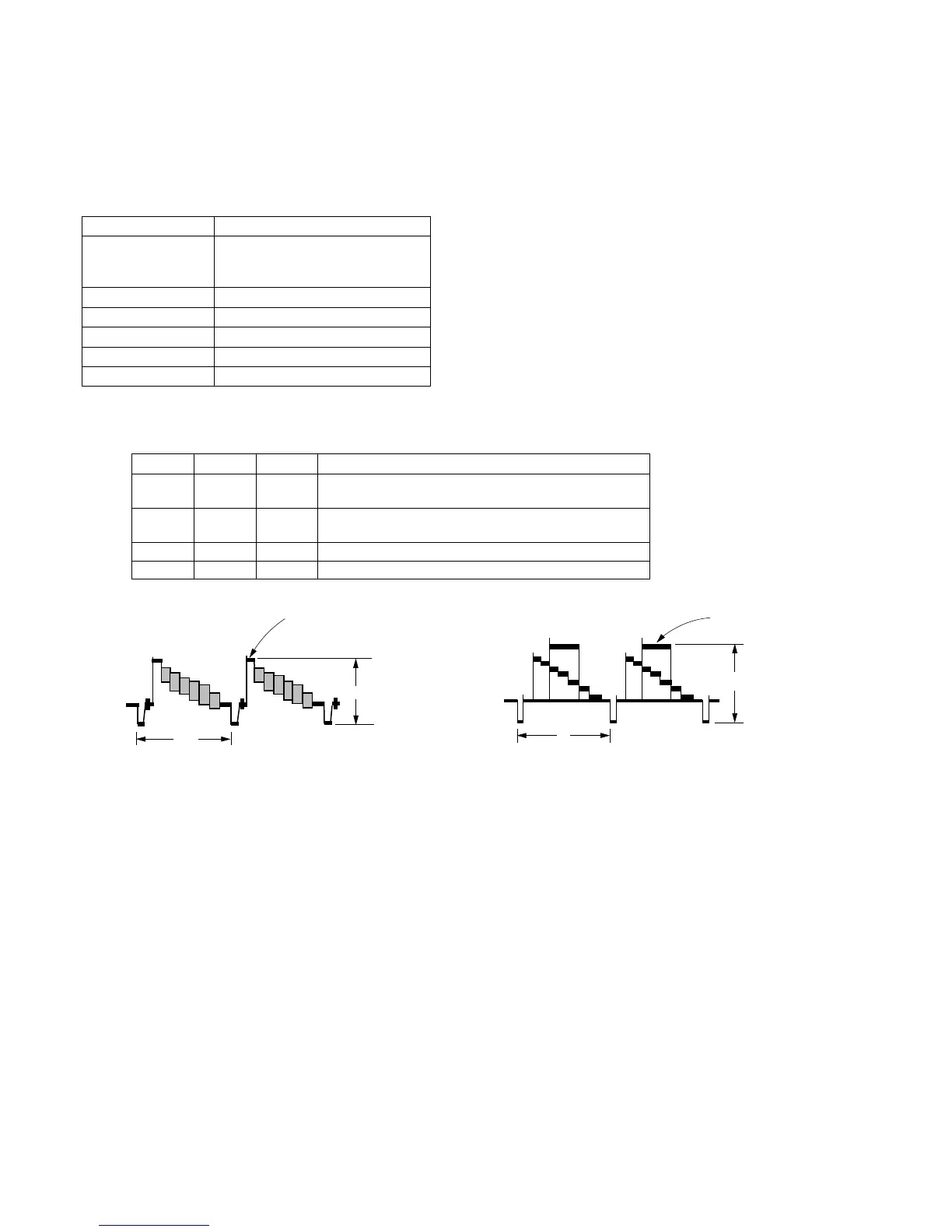
Specification Value A=0.50 ± 0.01Vp-p
Note : Minimize the residual chroma to the smallest amplitude
Adjustment procedure:
Related Adjustments:
“Emphasis input level adjustment”, “PB Y level adjustment”, “Y
FM carrier frequency adjustment”
Order Page Address Data Procedure
1 6 00 01 After setting the data, press the PAUSE button.
(Preparation)
2 F 3C Change data using PLAY and STOP buttons so that the
Y signal level (A) satisfies the specification.
3 Press the PAUSE button.
4 6 00 00 After setting the data, press the PAUSE button. (End)
H
White (100%)
A
White (100%)
H
A
PAL MODEL NTSC MODEL
Fig. 6-3-2