6-37
20-5. D RANGE adjustment (Type 2, 3 MODEL)
Purpose : Adjust to the proper LCD panel driving
dynamic range.
Adjustment Error :Image will be saturated (whitish) or blackish.
Mode Playback
Signal Color bar signal with chroma and
burst signals turned OFF.
Measuremant Point 〈CN1804〉 pin 2 (VG)
Measuring Instrument Oscilloscope
External trigger : 〈CN1804〉 pin 4
(HSY)
Adjustment Page F
Adjustment Address E0
Specfied Value Type 2 : A=3.60 ± 0.05Vp-p (PAL)
Type 3 : A=3.65 ± 0.05Vp-p (NTSC)
Adjustment procedure :
Order Page Address Data Procedure
1 6 00 01 After setting the data, press the PAUSE button. (Preparation)
2 F E0 Change the data of page : F address : E0, and adjust the amplitude level (A) of the VG
signal to the specified value. Amplitude : Level difference between the reverse waveform
pedestal and non-reversed waveform pedestal.
3 Press the PAUSE button.
4 6 00 00 After setting the data, press the PAUSE button. (End)
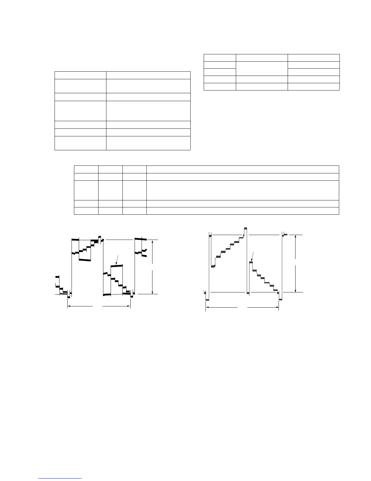
NTSC MODEL PAL MODEL
2H
2H2H
Pedestal level of
inverted waveform
Amplitude level A
Pedestal level of
non-inverted
waveform
White (100%)
2H
2H2H
Pedestal level of
inverted waveform
Amplitude level A
Pedestal level of
non-inverted
waveform
White (100%)
Note 1 : Set the BRIGHT control volume to their mechanical
center during adjustment.
Type 1
Type 2
Type 3
Type 4
LCD size
2.5 inch (PAL only)
3.0 inch (NTSC)
3.5 inch (NTSC/PAL)
LCD board
PD-74/SD-24
PD-75/SD-25
PD-77
PD-76
No mark : Type 1, Type 4
〈 〉 : Type 2, Type 3