6-62
2. Switching position adjustment
Purpose : Removes vertical mechanical error of head
assembling.
Adjustment error : Skew picture.
Mode Playback
Signal Alignment tape : For adjustment
tracking
WR5-1CP (PAL)
WR5-1NP (NTSC)
Measurement Point CH1 : 8 of CN102 (RF SWP)
CH2 : 1 of CN102 (PB RF)
Measuring Instrument Oscilloscope
Adjustment Page F
Adjustment Address 22, 23
* (24, 25)
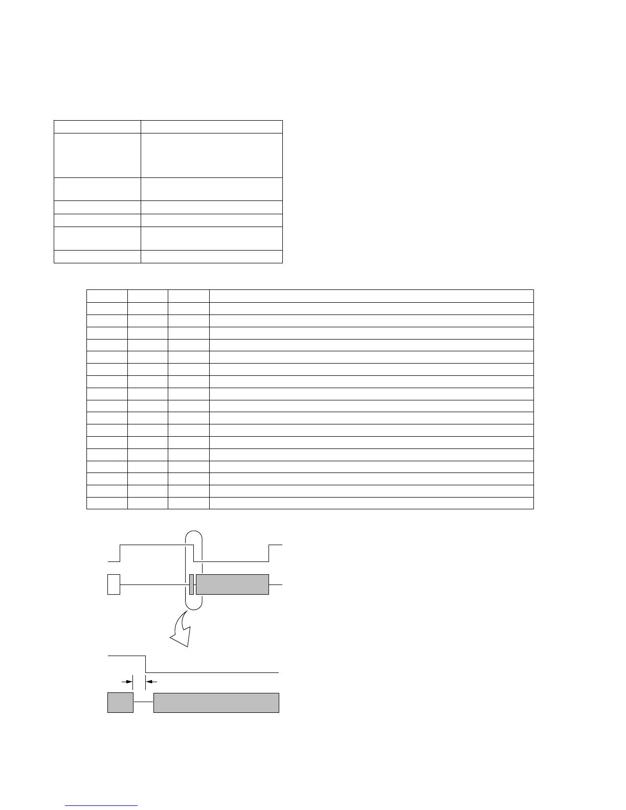
Specification Value t1= 0 ± 10µsec
Adjustment procedure:
CH1
CH2
Enlargement
t1
CH1
CH2
Order Page Address Data Procedure
1 6 00 01 After setting the data, press the PAUSE button. (Preparation)
2 F 23 80 Initial setting.
3 F 23 Change the data with the PLAY and STOP buttons, and minimize t1.
4 Press the PAUSE button.
5 F 22 Change the data with the PLAY and STOP buttons, and minimize t1.
6 Press the PAUSE button.
7 Check that t1 satisfies the specified value. If not, repeat steps 3 to 6 in order.
*8 F 01 Raed the data of page : F, address : 01, and record it.
*9 F 01 10 After setting the data, Press the PAUSE button. (Forced LP head selection)
*10 F 25 80 Initial setting.
*11 F 25 Change the data with the PLAY and STOP buttons, and minimize t1.
*12 Press the PAUSE button.
*13 F 24 Change the data with the PLAY and STOP buttons, and minimize t1.
*14 Press the PAUSE button.
*15 Check that t1 satisfies the specified value. If not, repeat steps 10 to 13 in order.
*16 F 01 Set the data which is recorded in step 8 to this address and press the PAUSE button.
17 6 00 00 After setting the data, press the PAUSE button. (End)
* : NTSC MODEL only