a.
Connector: DB-9
Outputs:
(3) RS-485 Outputs (Data Clocks, CTCSS frequencies, 1PPS)
(1) Alarm
Voltage:
Alarms: GND normally, high impedance when Alarm
b.
Connector: RJ-12
Outputs:
(1) RS-485 Outputs (Data Clocks, CTCSS frequencies, 1PPS)
(2) Alarm
Voltage:
Alarms: 5V pulled up through 10kΩ normally, GND when Alarm
Note: By factory default, all CTCSS outputs are DISABLED.
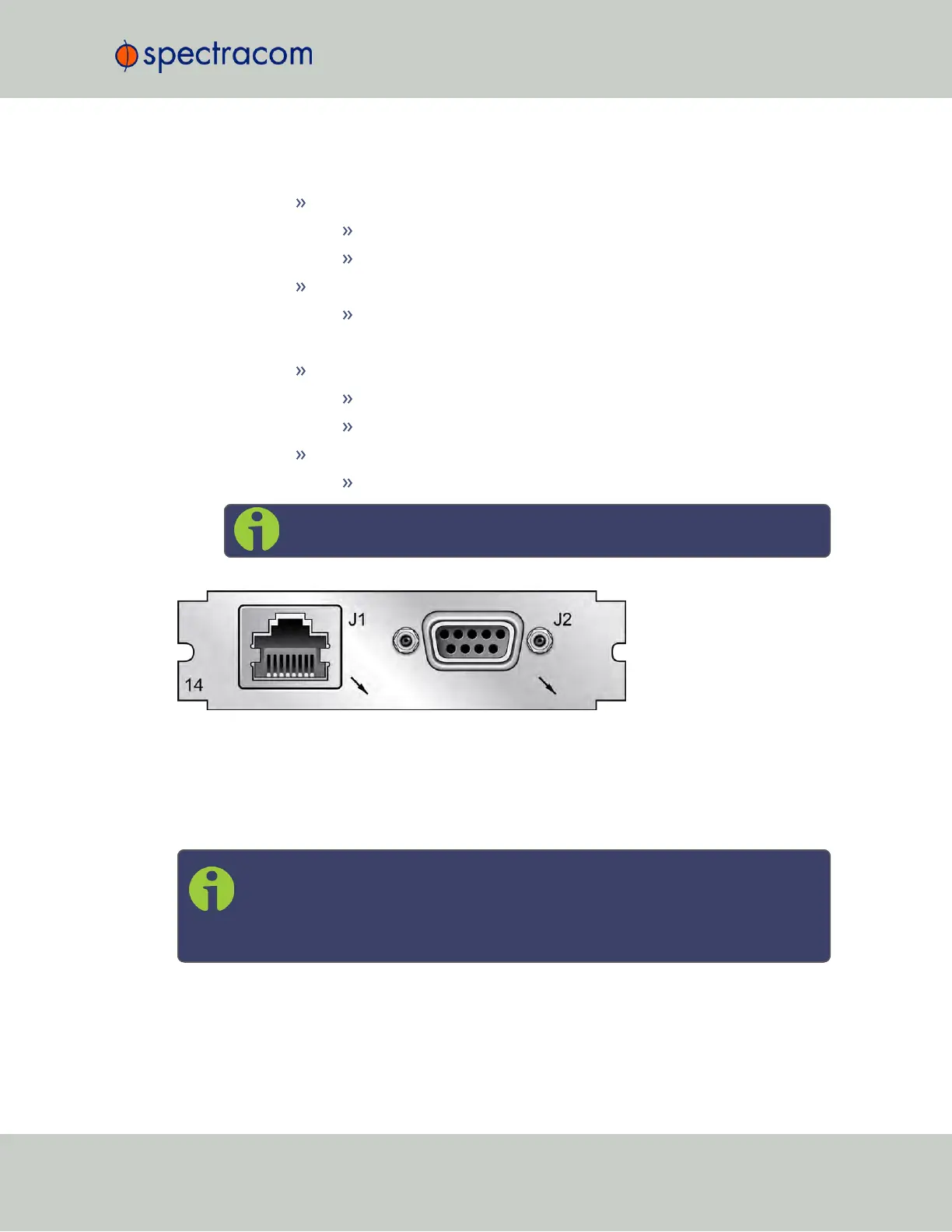
Figure 5-31: Model 1204-14 option card rear plate
Pin Assignment: DB-9 Connector
Outputs : Alarm0, CTC0 Out, CTC1 Out, CTC2 Out (with only one Simulcast option card
installed)
Note: Alarm Output 0 through Alarm Output 3 are reserved by SecureSync. In the
Web UI, numbering for alarm outputs for this option card will begin at Alarm 4,
which is available on the DB-9 output, while Alarms 5 and 6 are assigned to the
RJ-12 connector.
SecureSync User Reference Guide 381
APPENDIX