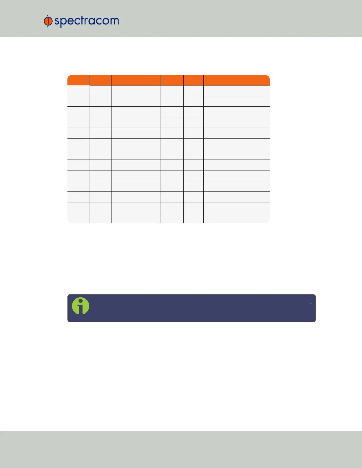
Pin Assignments
Pin No. Signal Function Pin No. Signal Function
1 GND Ground 14 TOD1- TOD1 RS-485- Out
2 TOD1+ TOD1 RS-485+ Out 15 NC -
3 NC - 16 NC -
4 TOD2+ TOD2 RS-485+ Out 17 TOD2- TOD2 RS-485- Out
5 NC - 18 NC -
6 GND Ground 19 NC 5MHz Out (1204-11 Only)
7 GND Ground 20 NC -
8 NC - 21 1PPS- 1PPS RS-485- Out
9 1PPS+ 1PPS RS-485+ Out 22 NC -
10 TFD Time Fault Discrete 23 GND Ground
11 TOD1 TOD1 TTL Out 24 1PPS 1PPS TTL Out
12 GND Ground 25 GND Ground
13 TOD2 TOD2 TTL Out
Table 5-18:
Models 1204-11, -25: DB-25 pin-out
STANAG Output: Edit Window
To configure a STANAG output, go to its Edit window. For instructions, see: "Configuring
Option Card Inputs/Outputs" on page330.
The Web UI list entries for these cards are: STANAG Out and STANAG Out, Isolated.
The outputs are named: Stanag HQ Output [number].
Note: SecureSync starts numbering I/O ports with 0 (only 1PPS and 10MHz out
puts start at1, because of the built-in outputs).
SecureSync User Reference Guide 415
APPENDIX