1.5 Connectors and their Pinouts
All of VersaSync's connectors are provided at the front panel of the unit, below the Status LEDs.
The Advanced Military Connectors are keyed for foolproof connectivity and offer a push-pull
locking mechanism.
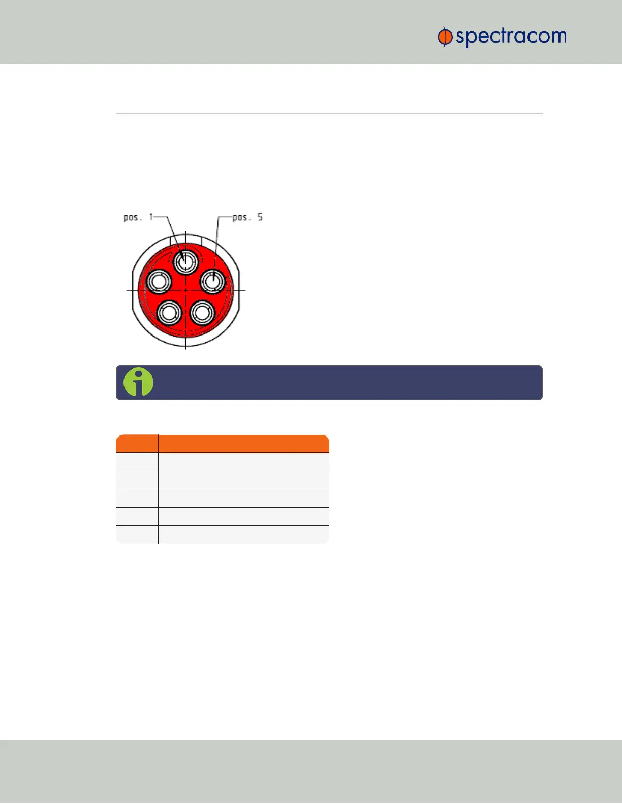
1.5.1 Power Connector
Note: View in mating direction from front.
Table 1-5:
Power connector pinout
Pin Signal
1 V
Main
(10 to 32V)
2 V
Main
(10 to 32 V)
3 V
Batt
(10 to 32 V)
4 GND
5 GND
1.5.2 Input/Output Connector
VersaSync has a 26- pin input/output connector that offers 8 software- configurable
CHANNELS, plus one fixed DCLS channel, and a USB interface. To learn more about types of
interfaces and signals, and how to configure them, see "Assigning I/O Pins" on page36.
8
CHAPTER 1 • VersaSync User Manual Rev. 6.0
1.5 Connectors and their Pinouts