5.4 IRIG Standards and Specifications
5.4.1 About the IRIG Output Resolution
The IRIG output signals are generated from VersaSync's System Time, which can be synced to
one or more external input references (such as GPS, IRIG, PTP, etc). The accuracy of the System
time to true UTC time is dependent upon what the selected external reference is (with GPS typ-
ically being the most accurate reference for the system to sync with).
As for the four available IRIG outputs of the 1204-15 Option Card, outputting an IRIG DCLS
(Phase Modulation) signal provides much better and more accurate synchronization of another
device than does an IRIG AM (Amplitude Modulation) signal. This is due to the faster rise-time
with the DCLS signal being able to provide a more “crisp” on-time point (more distinct, with
less jitter) than the slower rise-time of an AM modulated signal.
IRIG AM synchronization of a device to its IRIG source is typically measured in the tens of micro-
seconds, while synchronization using a IRIG DCLS signal can typically provide around 100
nanoseconds or so (plus the cable delays between VersaSync and the other device, as well as
the processing delays of the other system itself).
Note that each of the four IRIG outputs of the Model 1204-15 card has its own available ‘offset’
capability, which is configurable via VersaSync’s WebUI, to help account for cabling and pro-
cessing delays of the device each output is connected with.
5.4.2 IRIG Carrier Frequencies
Each IRIG code specifies a carrier frequency that is modulated to encode date and time, as well
as control bits to time-stamp events. Initially, IRIG applications were primarily military and gov-
ernment associated. Today, IRIG is commonly used to synchronize voice loggers, recall record-
ers, and sequential event loggers found in emergency dispatch centers and power utilities.
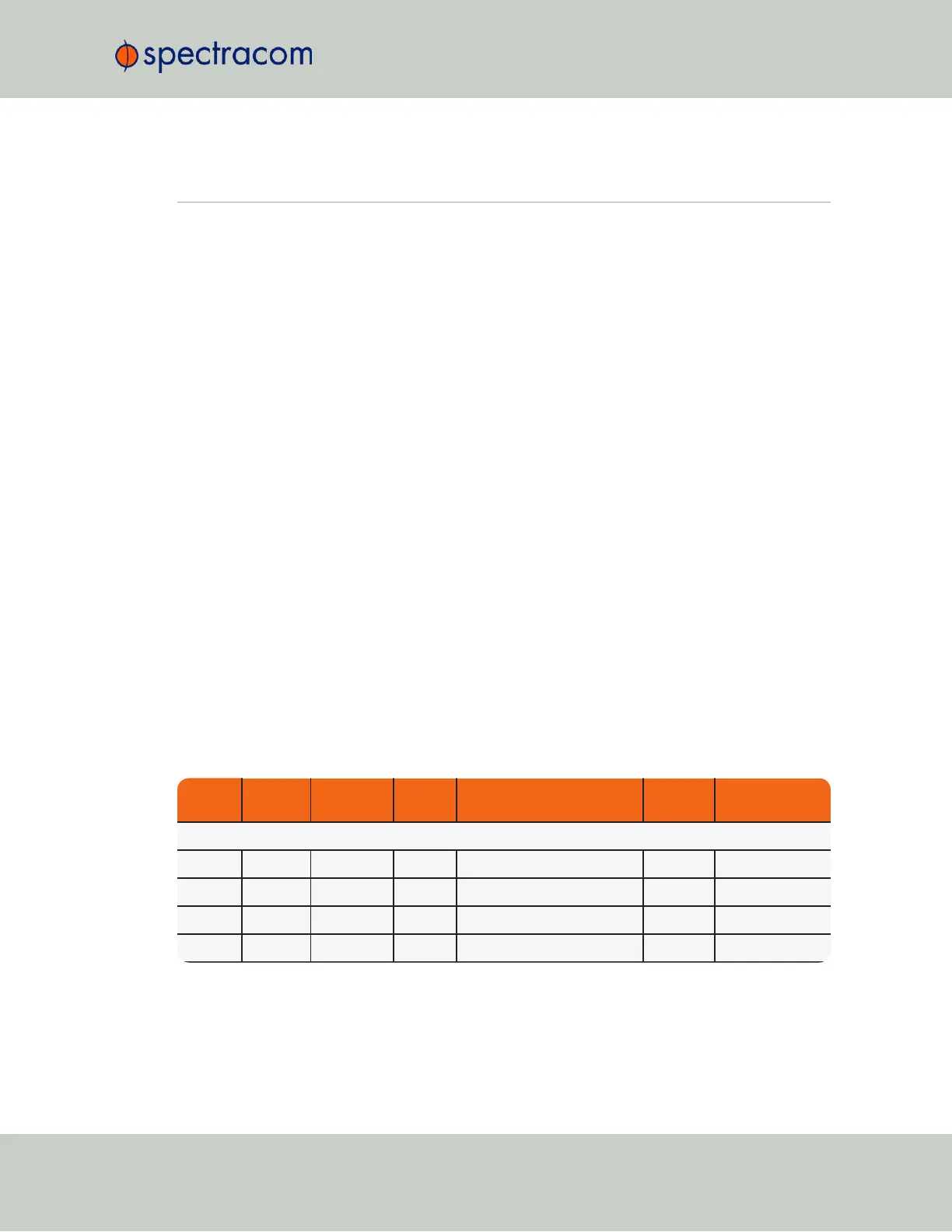
Table 5-4:
Available IRIG output signals
Format Encoding Modulation Carrier Coded Expressions Bit rate
Time Frame Inter-
val
IRIG-A
IRIG-A A000 DCLS N/A BCD
TOY
, CF and SBS 1000 pps 0.1 sec
IRIG-A A001 DCLS N/A BCD
TOY
, CF 1000 pps 0.1 sec
IRIG-A A002 DCLS N/A BCD
TOY
1000 pps 0.1 sec
IRIG-A A003 DCLS N/A BCD
TOY
, SBS 1000 pps 0.1 sec
VersaSync User Manual 273
APPENDIX