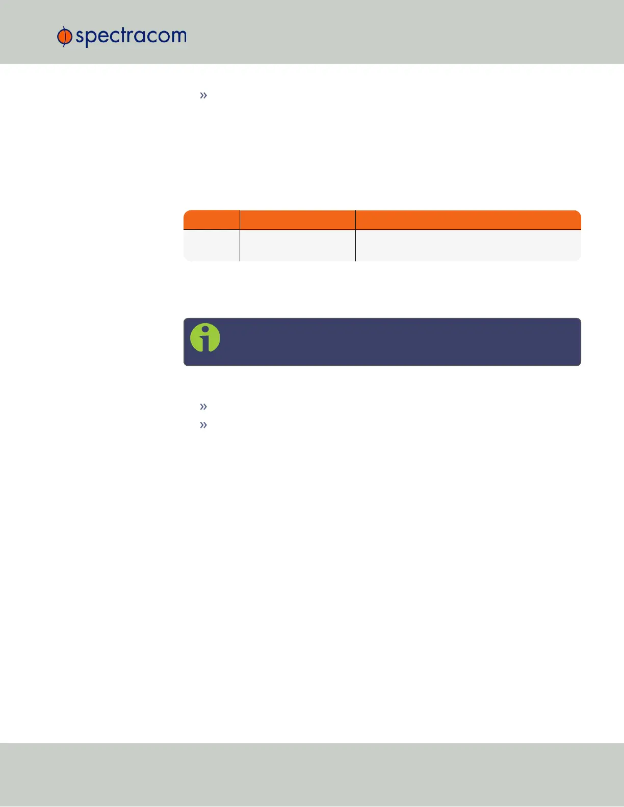
Ethernet: Connect the Ethernet cable to the ETH port of the unit. If you are using
the Evaluation Kit, connect at least one of the two I/O cable Ethernet ports (ETH0
or ETH1) to a network switch/hub, or to the PC mentioned above (using a stand-
ard Ethernet patch cable, or a crossover cable.)
For pinout tables, see "Connectors and their Pinouts" on page8 and "Configuring Input-
s/Outputs" on page35.
4.
Connect the power supply. The unit will power up, and the ON/OFF status LED will
pulsate.
Requirement Action Evaluation kit cable
Power up Connect 12 V
DC
to the
power connector.
Attach a cable and apply 12 V
DC
to the plug labeled
"Main" (CA08R-CRPB-0002)
5.
Establish a network connection so as to allow access to the web user interface ("Web UI").
See "Initial Network Setup" on page27 for information on the USB driver installation
and network address configuration.
Note: On a DHCP network, you can also use Zeroconf to access the Web
UI (see "Zero Configuration Setup" on page30).
6.
Using the Web UI, configure the following:
Software-configurable I/O pins, see "Assigning I/O Pins" on page36.
Other VersaSync INTERFACES settings and MANAGEMENT settings e.g., network
settings, reference priorities (see "Configuring Network Settings" on page54).
2.1.2 Mounting
2.1.2.1 Selecting a Mounting Location
The unit is to be mounted on a plate, using six (6) through holes. The mounting location must
offer sufficient space to accommodate the unit and the cable connectors, and it must be within
cable reach to other connected devices, such as the GNSS antenna. The unit can be mounted
horizontally, or at any angle. The chosen environment must not fall below IP 65 ingress pro-
tection standards.
2.1 Installation Overview
CHAPTER 2 • VersaSync User Manual Rev. 6.0
25