2.1 Installation Overview
The steps that need to be performed prior to putting VersaSync into service include:
Installation: Hardware setup, mechanical installation, physical connections.
Setup: Establish basic access to the unit, so as to allow the use of the web user interface
("WebUI").
Configuration: Access the Web UI, configure the network, input and output references,
protocols (e.g., NTP), other settings.
Not all of the setup steps described in this manual may apply to you. Your unit installation rel-
ative to other connected devices, the cable selection and manufacturing, your chosen power
source, your project-specific infrastructure, and your planned access to your unit (either WebUI
or CLI), could all affect your setup needs.
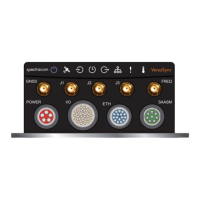
2.1.1 Hardware Connections
During the procedure described below, you will connect the Power cable, the Multi I/O cable,
and the Ethernet cable.
The step-by-step instructions below outline the VersaSync installation and configuration process:
1.
Install VersaSync in the designated vehicle:
Ground the unit by connecting the DC negative terminals to the chassis of the unit,
and to the vehicle metallic structure.
The mounting plate should be in direct contact with the unit base plate, so as to
conduct heat.
For more detail on mounting your unit, see "Mounting" on the facing page.
2.
Install the GNSS antenna(s).
3.
Wire the antenna cables and interface cables. Most customers will require the Multi I/O
and Ethernet cables for these connections, as well as a PC..
Requirement Action Evaluation kit cable
USB con-
nection
Connect USB to the Multi I/O
connector.
Connect the USB connector to a PC with a terminal
emulator program (CA08R-CRUB-0002)
Network
connection
Connect at least one of the
two Ethernet connectors to a
network.
Connect the RJ45 jack labeled ETH0 or ETH1 to a
network hub/switch or directly to a PC (CA08R-
CRET-0002)
USB: Connect the Multi I/O connector to the VersaSync unit. If you are using the
Evaluation Kit, connect the Multi I/O USB output to a PC. Install a terminal emu-
lator program on the PC (e.g., TeraTerm
®
or PuTTY
®
).
24
CHAPTER 2 • VersaSync User Manual Rev. 6.0
2.1 Installation Overview