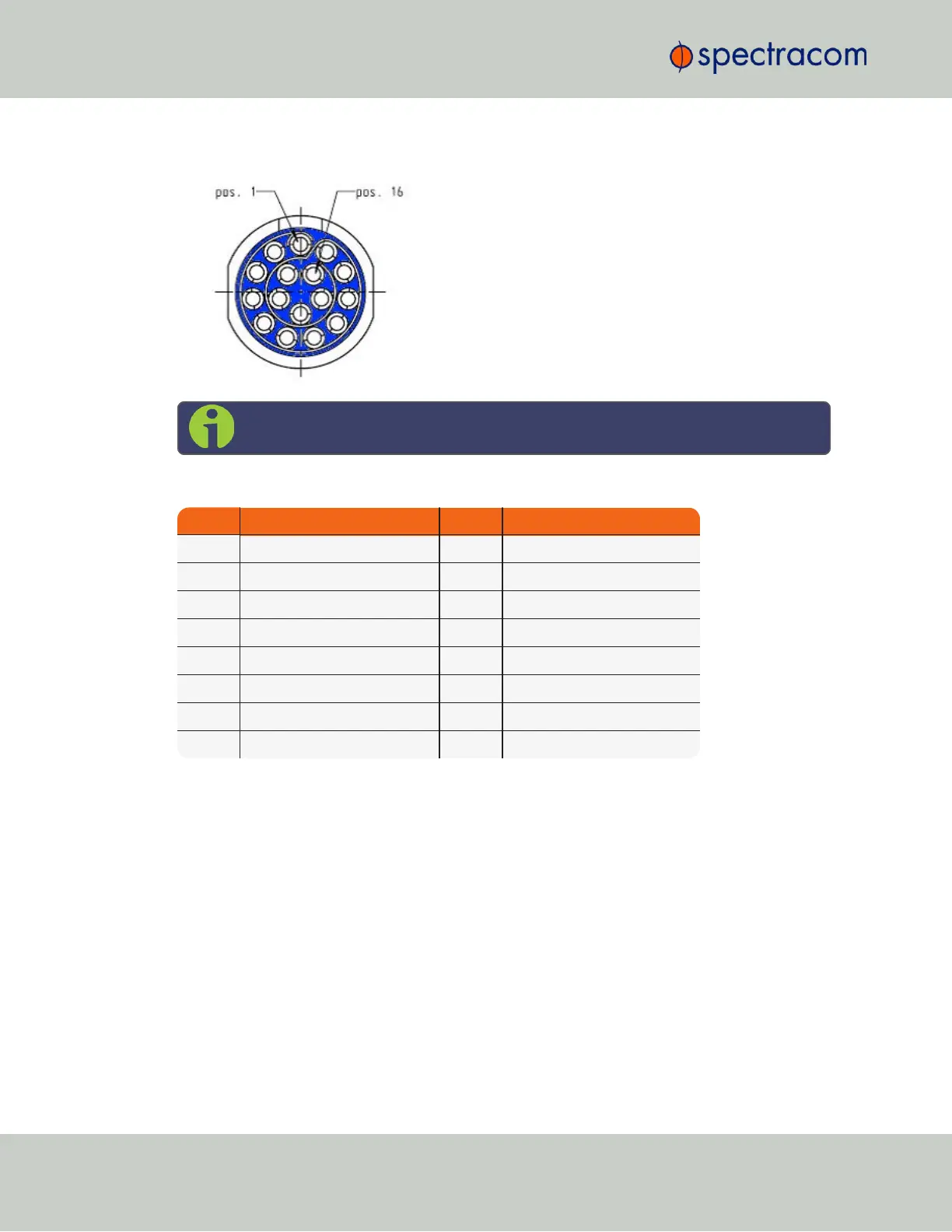
1.5.3 Ethernet Connector
Note: View in mating direction from front.
Table 1-7:
Ethernet connector pinout
Pin Signal Pin Signal
1 Ethernet_1 A+ 9 Ethernet_2 A+
2 Ethernet_1 A– 10 Ethernet_2 A–
3 Ethernet_1 B+ 11 Ethernet_2 B+
4 Ethernet_1 B– 12 Ethernet_2 B–
5 Ethernet_1 C+ 13 Ethernet_2 C+
6 Ethernet_1 C– 14 Ethernet_2 C–
7 Ethernet_1 D+ 15 Ethernet_2 D+
8 Ethernet_1 D– 16 Ethernet_2 D–
1.5.4 Optional I/O Connector
The Optional I/O connector is used in conjunction with the Option Board that is available for
VersaSync. If the unit is not equipped with an Option Board, this connector is not used.
1.5.5 Coaxial Connectors
VersaSync offers five (5) coaxial connectors, three (3) of which can be configured at the fact-
ory to accommodate requirements for e.g., IRIG AM signals or additional 10MHz outputs. The
minimum configuration includes the GNSS antenna and a 10MHz sinewave output.
Unless otherwise ordered at the factory, all coaxial connectors (aside from the GNSS con-
nection) produce a 10MHz output that is not software configurable.
All coaxial connectors are standard SMA connectors.
10
CHAPTER 1 • VersaSync User Manual Rev. 6.0
1.5 Connectors and their Pinouts