Customer Replaceable Units Right and Left Side Louver Panels
Page 165
© Copyright 2020 Stratasys. All rights reserved.
Right and Left Side Louver Panels
Required Tools
• 3mm hex wrench
Removing the Louver Panels
1. Power OFF the printer. See Powering Off on page 5-5.
2. Remove the rear panel. See “Removing the Rear Panel” (page 161).
3. Remove the right side panel. See “
Removing the Side Panels” (page 162).
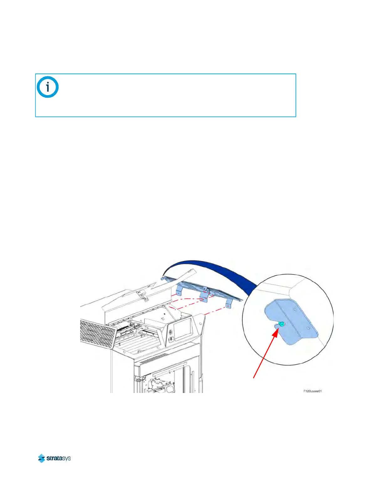
4. Using a 3 mm hex wrench, remove the right side louver panel mounting screws (3) that
s
ecure the louver panel to the cover support bracket. See Figure 20 (page 165).
5. Using a 3 mm hex wrench, remove the right side louver panel mounting screws (2) that
s
ecure the louver panel to the cover buttress. See Figure 20 (page 165).
6. Gently pull the louver panel away from printer until the formed bracket disengages from the
r
ear cover standoff fastener. See Figure 20 (page 165).
Figure 20: Louver Panel Location (Right Side Shown)
7. Remove the louver panel from the printer.
Note:
The following procedure describes and depicts replacement of the right side louver
panel only. The left side louver panel replacement procedure is identical to the right
side panel replacement procedure except that the left side panel must be removed for
access.
Rear Cover
Standoff Fastener