116
S
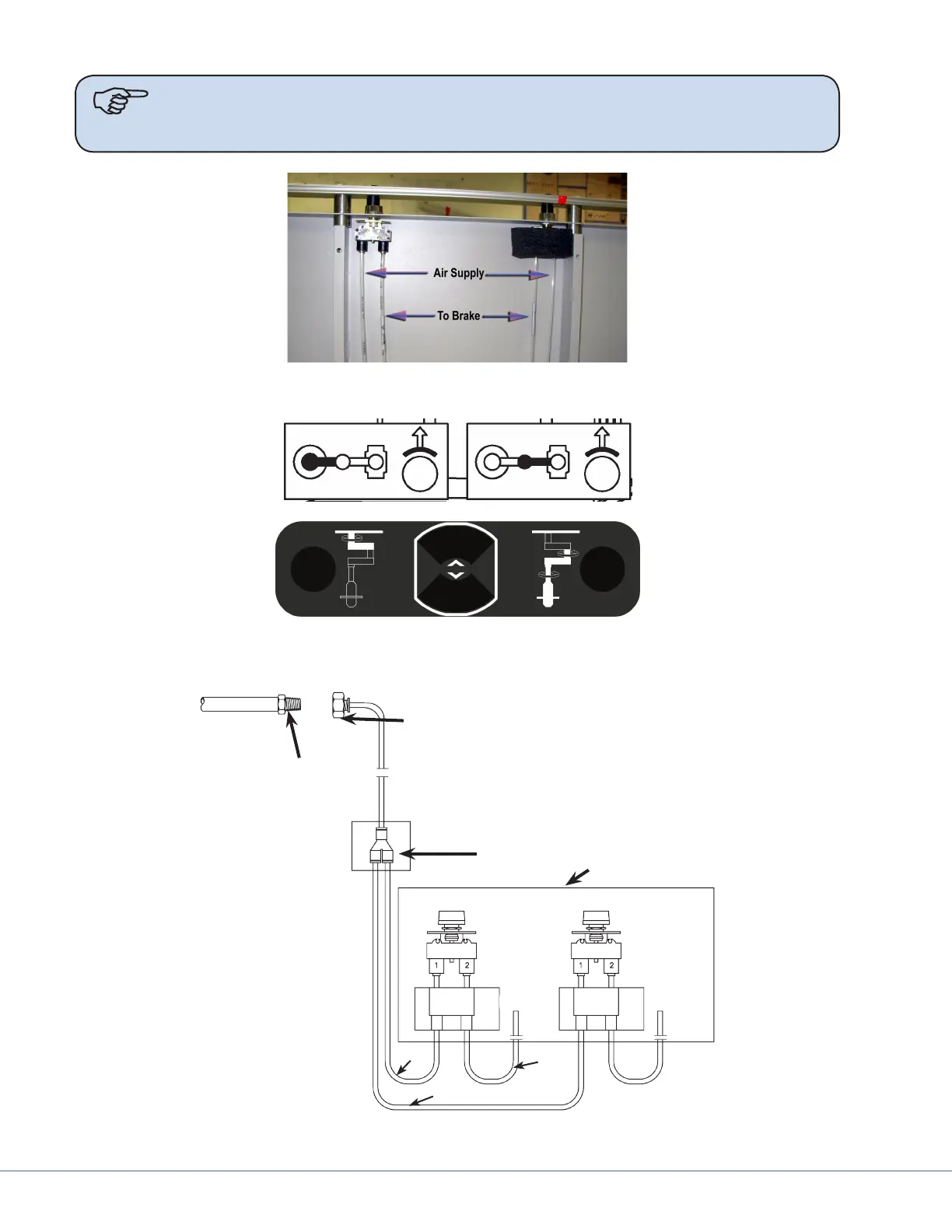
Note e mounting of the air valves on the shelf has one valve reversed. is causes
both outside lines to be supply lines and the inner lines to be bladder connec-
tions. e foam around the valves is for noise reduction while venting.
Foam removed from Le Air Valve for illustration purposes.
e symbols above are used to identify each brake. e Le hand symbol refers to the upper brake. e
symbol on the right indicates the lower brake. ese are used to label the air valves and the tubing.
Left Button Upper Arm
Right Button Upper Arm
Upper Arm
Lower Arm
3000mm
4200mm
800mm
800mm
Shelf
Customer supplied
brake supply line
12mm Ø Brake inlet hose:
(May be tted with a connector if
specied at time of order)
Service Head
Diagram of Brake System for Stryker Articulating Equipment Booms for Legacy Systems