139
S
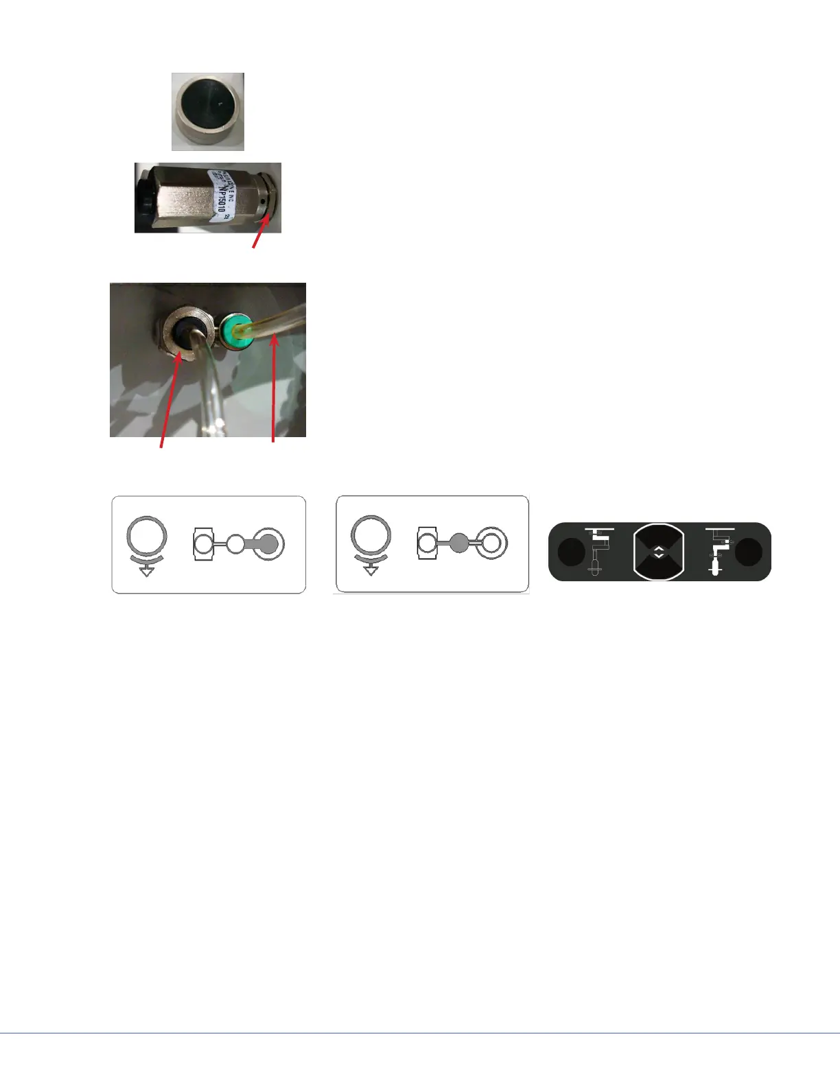
11. Screw the button onto the Solenoid.
Adjustment Nut
12. Adjust the lock nut from behind to tighten the assembly.
13. Repeat the procedure for the second button.
Supply or Shelf
(if used)
To Brake
14. It there is only one button in the Service Head, insert the sup-
ply tubing into the Center Solenoid Connection.
15. Insert the Brake Bladder tubing in the outboard Solenoid
Connector.
16. Turn on the air supply.
17. Verify that no leaks can be heard.
Ceiling Brake
Mid Brake
FLEXiS Brake Buttons
18. Verify the operation matches the label on the rail to the tubing coming from the green port on
matching the Solenoid of the shelf brake.