29
S
• Insert the light head into the Spring Arm. Make sure to support the Spring Arm when as-
sembling.
5. Reinsert the retaining screws removed in steps 2 and 3.
WARNING e cu must be in place before installing the retaining screws.
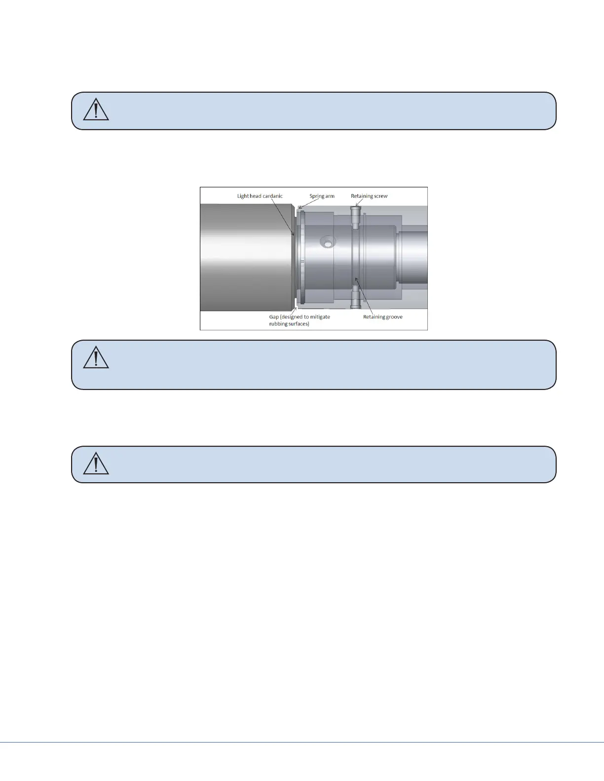
• Align the retaining ring groove feature on the Cardanic of the light head with the retaining
screw holes in the spring arm. A gap will be present between the face of the Cardanic and
face of the spring arm when properly aligned. If needed, back the light head out slightly.
Caution Tightening the retaining screws into the wall of the Cardanic without
aligning them into the retaining ring groove may damage the surface of the
Cardanic.
• Place the rst retaining screw through the opening of the cu and reinstall it. Tighten the
screw completely to ensure that the cu will still rotate freely.
• Rotate the cu 180° to reinstall the second retaining screw. Tighten completely.
Caution Over tightening the Low Ceiling light head to Spring Arm brake screw can
cause permanent damage to the light
• Rotate the cu 90° to insert the brake screw back into place. Tighten the screw until the light
head constantly holds the position in which it is placed.
• When adjusting the brake screw aer installing the light for the rst time or any time aer
performing preventative maintenance, adjust the brake screw and rotate the joint through
a minimum of ve rotations. If aer ve rotations the joint becomes dicult to rotate, the
brake screw is over tightened and needs to be readjusted.
8.1.2.2 Low Ceiling 9-Pole Light Head
1. Locate the 9-pole Spring Arm and remove the brake screw.
2. Rotate the cu 90° to reveal the rst retaining screw. Remove the retaining screw from the
Spring Arm.
3. Rotate the cu 180° to reveal the second retaining screw. Remove the retaining screw from the
Spring Arm.
4. Install the 9-pole light head. Make sure to support the Spring Arm when assembling.