74
S
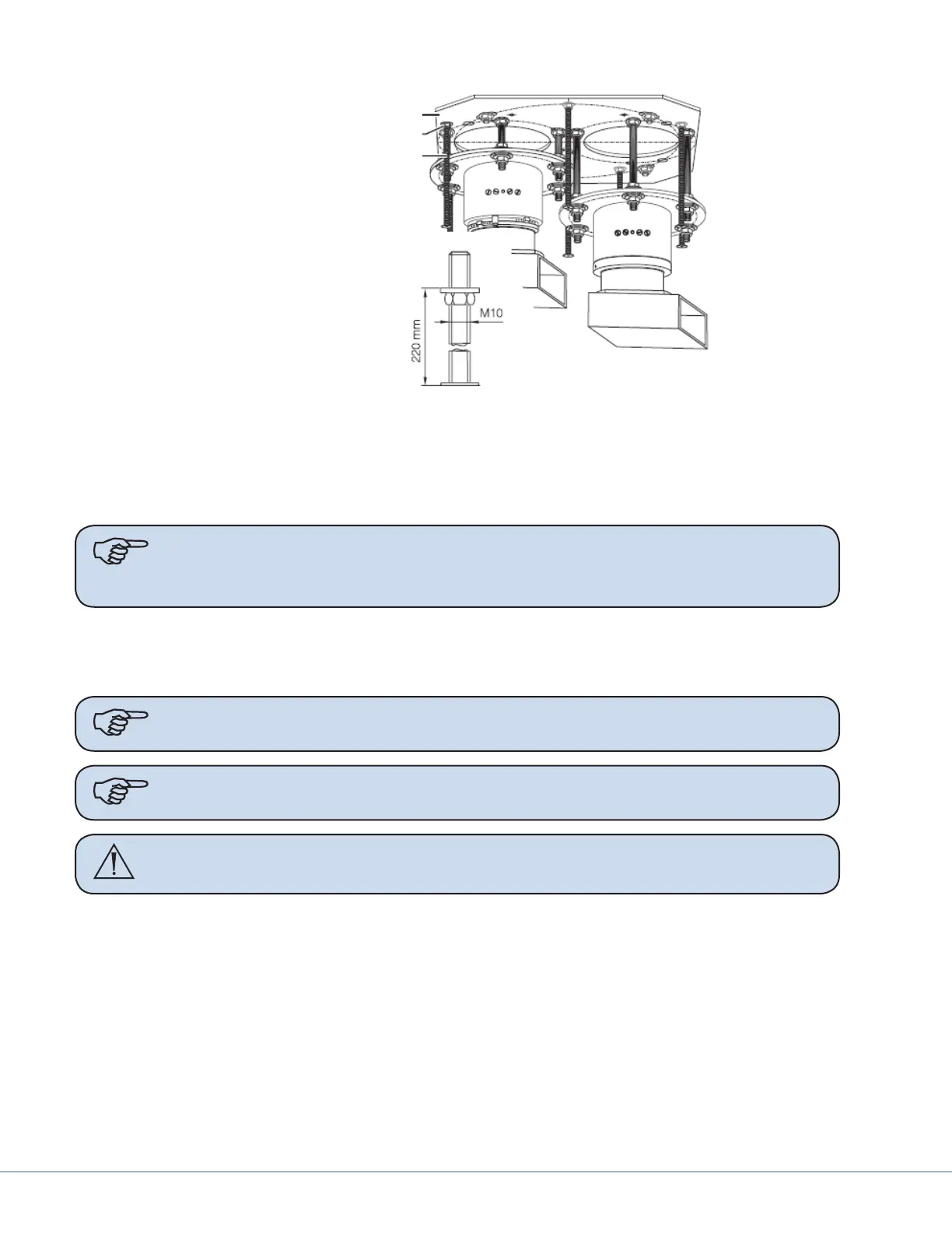
Interface Plate
Hexagon nut M10 with washer
Threaded bolt M10 X 360 mm
Ceiling Cover Installation
3. Align the mounting holes of the ceiling cover halves (#4 in the gure) with the threaded bolts
(#3 in the gure) and join the two halves (#4 in the gure) using the cover tabs. e tops of the
ceiling cover halves should be ush with the ceiling.
Note Covers have two holes for tandem congurations. Use reducer rings to match
cover diameter to mounting ange diameter. Use hole cover when single boom is
mounted.
4. Secure the ceiling cover halves (#4 in the gure) by screwing the six cover retaining screws (#1
in the gure) into the threaded bolts.
5. Check ceiling cover halves (#4 in the gure) for secure fastening.
Note If cover does not t due to interference with boom parts, the boom may need to
be repositioned on the all-thread rods.
Note Ceiling cover may be circular.
Warning Improper installation of the Ceiling Covers may result in them potentially
falling into the sterile eld.