82 SPARCstation 20 Service Manual • July 1996
FIGURE 8-24 Routing Excess Cables in Cable Trough
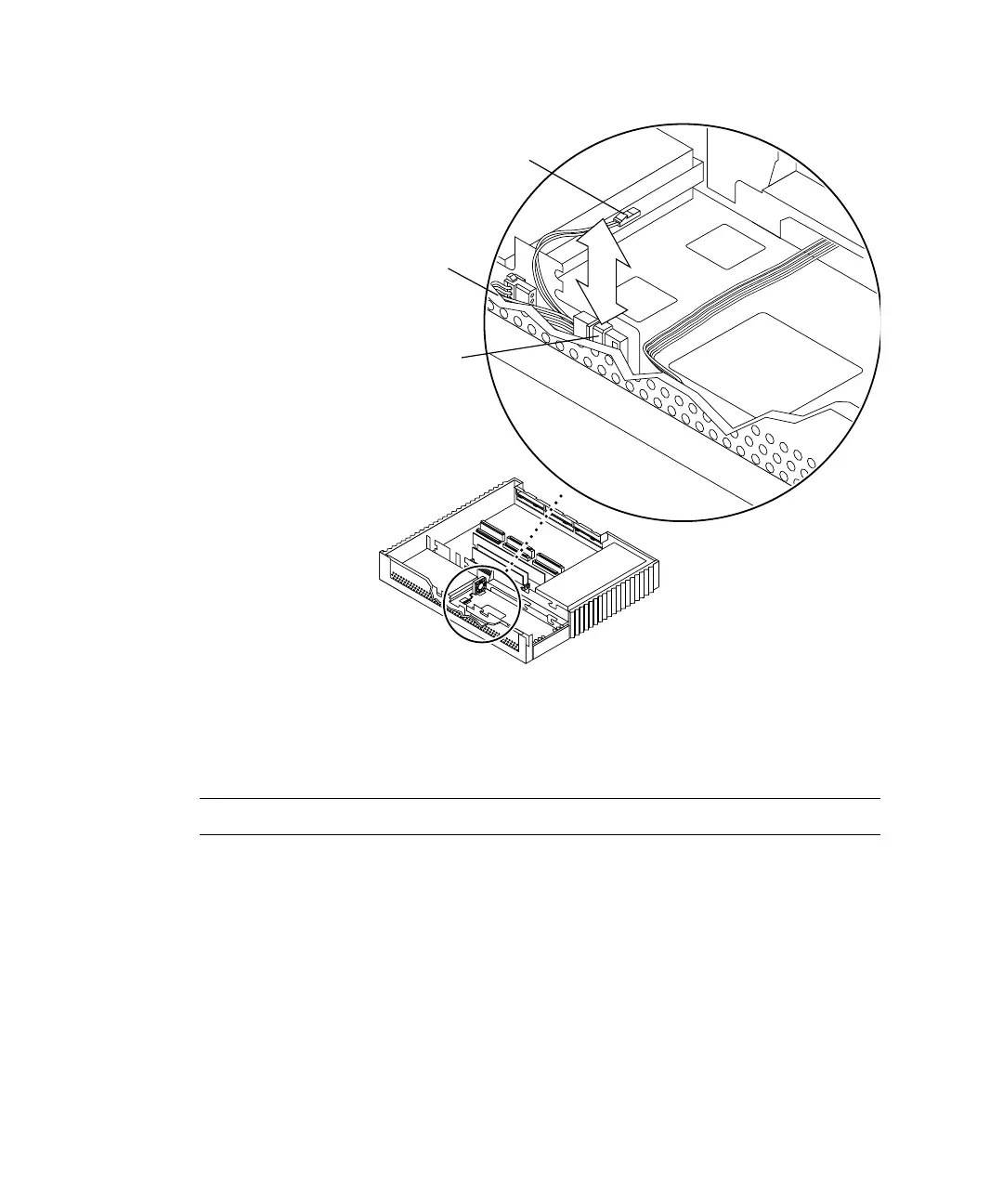
4. Connect the two-pin power connector to the fan assembly DC power connector
(
FIGURE 8-25).
Note – Connectors and terminals are keyed to ensure proper connection.
5. Detach the wrist strap and replace the cover.
See Chapter 7.
6. Power on the system.
See “Turning On the Power” on page 47.
Fan DC power
Front
Cable
trough
Right side
connector
CD-ROM drive
DC power
connector
Note: Cable restraints and SCSI data
cables are not illustrated.