90 SPARCstation 20 Service Manual • July 1996
4. Remove any SBus cards.
See “Removing an SBus Card” on page 152.
5. Loosen the two captive screws on the back panel that secure the system board to
the chassis (
FIGURE 8-30).
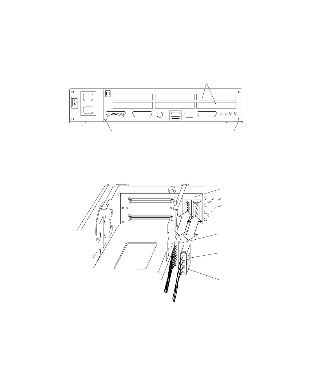
FIGURE 8-30 Back Panel SBus Slots and Captive Screws
6. Press the plastic connector clip and disconnect the DC power connector from the
SCSI backplane (
FIGURE 8-31).
FIGURE 8-31 SCSI Backplane, SCSI Data, and DC Power Connectors
7. Slide the system board back slightly to access the internal cables.
Captive screw
Captive screw
SBus slots
2 and 3
DC power
connector clip
SCSI data
connector (P3)
SCSI backplane
DC power
connector (P1)