176 SPARCstation 20 Service Manual • July 1996
Note – Do not overtighten captive screws.
5. Ensure that the configuration of the replacement system board is identical to the
removed system board. Remove any SBus or MBus filler panels from the
replacement system board, as necessary.
6. Replace the following:
■ NVRAM/TOD (see “Installing a NVRAM/TOD” on page 181)
■ AVB (see “Auxiliary Video Board” on page 168)
■ SIMMs (see “DSIMMs, VSIMMs, and NVSIMMs” on page 159)
■ SBus cards (see “SBus Card” on page 152)
■ MBus modules (see “MBus Module” on page 143)
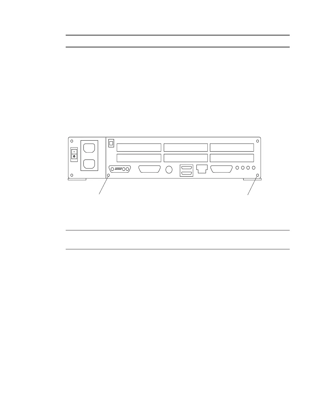
FIGURE 11-41 System Board Captive Screws
Note – It is not necessary to remove the OpenBoot PROM from the defective board.
The new system board already has the correct OpenBoot PROM installed.
7. Connect the following to the system board (
FIGURE 11-42):
■ Diskette connector (optional)
■ SCSI connector
■ DC power connector
■ Speaker/LED connector
8. Remove the wrist strap and replace the cover.
See Chapter 7.
9. Turn on system power.
See Chapter 6.
Captive screw
Captive screw