94 SPARCstation 20 Service Manual • July 1996
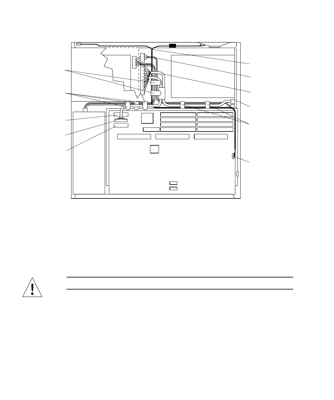
FIGURE 8-33 Internal Cables and DC Power Connector (SunCD 4 Drive-Type Chassis)
4. Loosen the two captive Phillips-head screws that secure the system board to the
rear chassis (
FIGURE 8-34).
5. Pull the system board from the back of the chassis until it clears the plastic
card guide (
FIGURE 8-34).
Caution – Place the system board on an antistatic surface.
6. Remove the SunCD 4 CD-ROM drive.
See “Removing a CD-ROM Drive” on page 123.
Speaker/LED
connector
Card guide
cable clip (2)
Cable clip (3)
(located on
Cable clip (2)
(located on
Diskette data
connector
SCSI data
connector
DC power
connector
Speaker/LED
cable
DC power
harness
SCSI data
cable
SCSI
backplane
Note: Figure illustrates SunCD 4 drive-type (1.6-inch drive) chassis only.
chassis floor)
chassis wall)