104 SPARCstation 20 Service Manual • July 1996
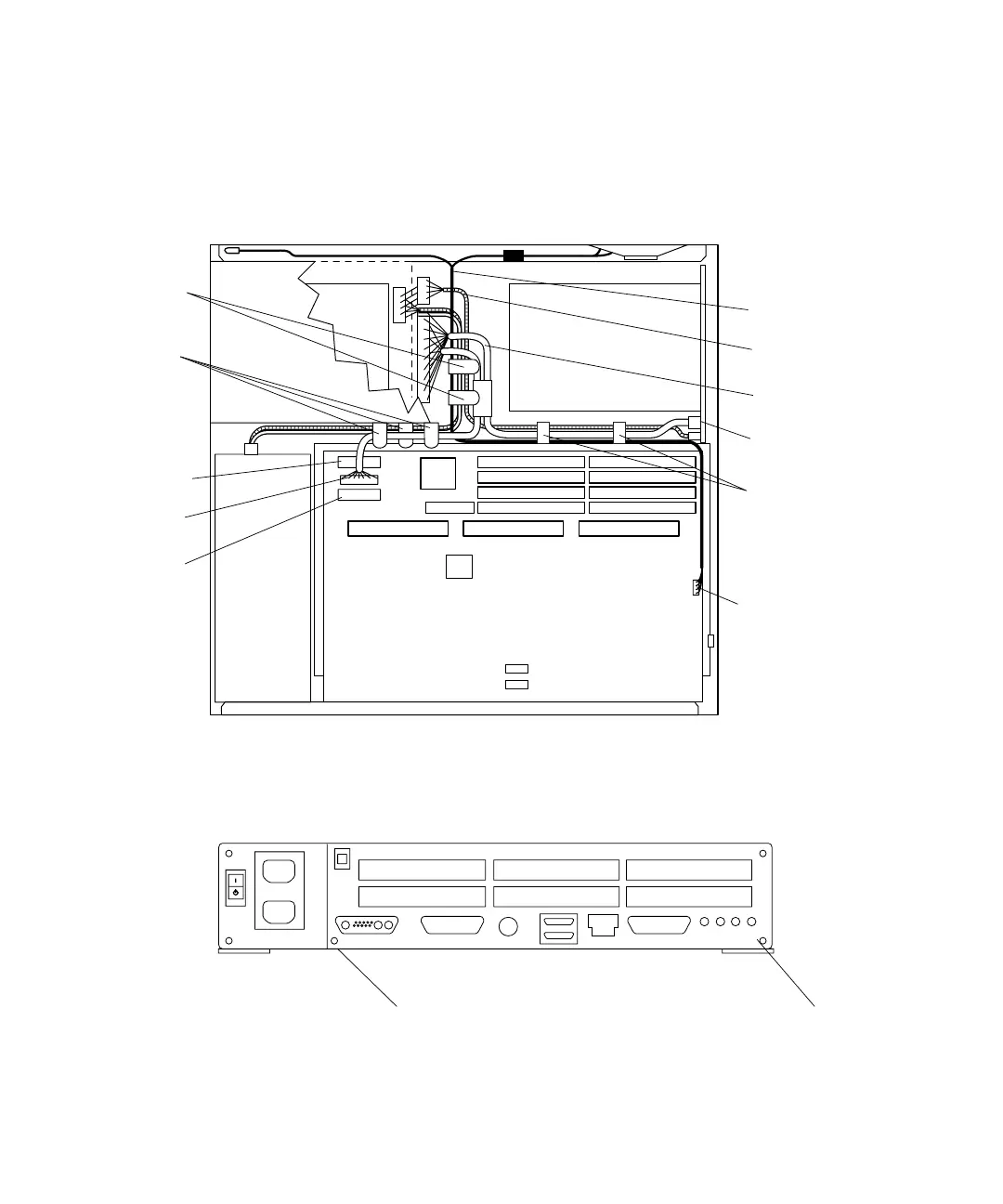
3. Disconnect the DC power cable, SCSI data cable, diskette data cable, and speaker/
LED cable from the system board (
FIGURE 8-40).
4. Loosen the two captive Phillips-head screws that secure the system board to the
chassis rear (
FIGURE 8-41).
FIGURE 8-40 Internal Cables and DC Power Connector (SunCD 4 Drive-Type Chassis)
FIGURE 8-41 Back Panel Captive Screws
Speaker/LED
connector
Card guide
cable clip (2)
Cable clip (3)
(located on
Cable clip (2)
(located on
)
Diskette data
connector
SCSI data
connector
DC power
connector
Speaker/LED
cable
DC power
harness
SCSI data
cable
SCSI
backplane
Note: Figure illustrates SunCD 4 drive-type (1.6-inch drive) chassis only.
chassis floor
chassis wall)
Captive screw
Captive screw