Chapter 4 Troubleshooting Procedures 31
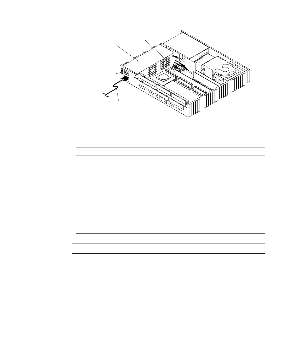
FIGURE 4-2 Power Supply and Power Supply Connector Location
Note – All voltages are correct if they are within the +5% or –5% range.
System Board Test
To test the system board:
TABLE 4-2 Power Supply Connector Pin Assignments
Pin Color Description Pin Color Description
1 Blue +12 10 Black Ground
2 Brown -12 11 Black Ground
3 Red +5 12 Black Ground
4 Red +5 13 Black Ground
5 Red +5 14 Black Ground
6 Red +5 15 Black Ground
7 Red +5 16 Green AC Outlet
8 Red +5 17 Purple Fan
9 Grey Power Off 18 Yellow Power On
Power supply
External power
cord
Power supply
connector
Power-on/standby
switch