Chapter 11 System Board and Component Replacement 173
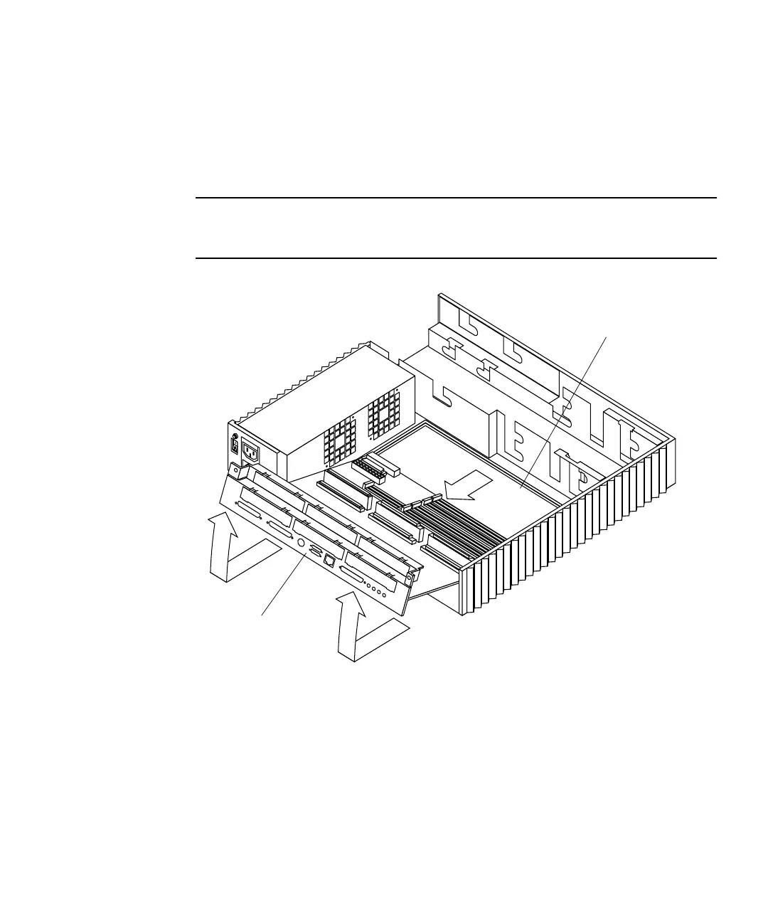
6. Slide the system board toward the back of the chassis until it clears the plastic
card guide (
FIGURE 11-38).
7. Lift the back of the system board slightly. Slide the system board clear of the
plastic card guide and out of the chassis.
8. Place the system board on an antistatic surface.
Note – If a captive screw is in the upper right corner of the system board back
panel, remove the screw by backing it out of the plastic back panel cover. This screw
will be needed to secure the top cover to the chassis.
FIGURE 11-38 Removing the System Board
Jumper Settings
Verify the jumper settings of the clock speed jumper (J1401) and the serial port
jumpers (J0801 and J0802) on the system board before installation. The jumpers are
preset at the factory as shown in
FIGURE 11-39.
Card guide
System board