92 SPARCstation 20 Service Manual • July 1996
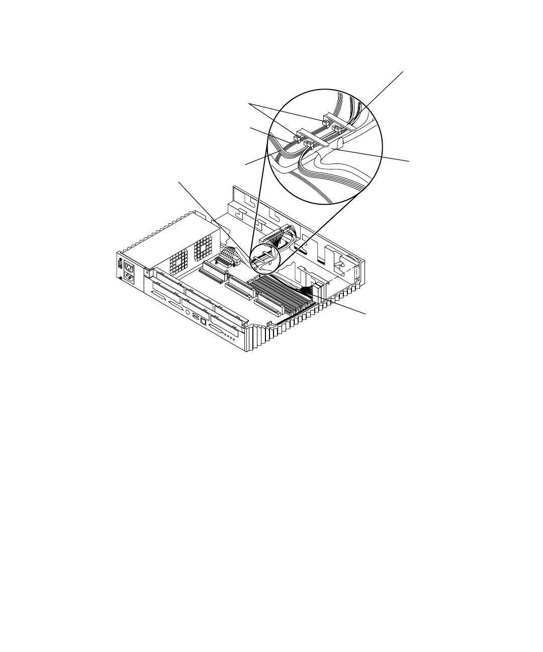
FIGURE 8-32 Cable Guide Detail
2. Connect the following cables to the SCSI backplane (FIGURE 8-31):
a. SCSI data connector (P3)
b. DC power connector (P1).
3. Replace the SunCD 2Plus CD-ROM drive.
See “Installing a CD-ROM Drive” on page 124.
4. Position the system board into place and tighten the two captive screws on the
back panel that secure the system board to the chassis (
FIGURE 8-34).
5. Replace any SBus cards (see
FIGURE 8-37).
See “Installing an SBus Card” on page 156.
6. Connect the following cables to the system board (
FIGURE 8-40):
■ Speaker/LED cable
Tie-wrap markers
Metal cable guide
SCSI data
cable marker
Speaker/LED
harness
DC power
harness
Drive bracket
sheetmetal
opening
Card guide
plastic hooks