G10 Hardware Maintenance Guide 7.13.2 107
5
Maintenance Guidelines
Rev. 002-140228
4. If you are removing the blade perform the following:
Loosen the thumbscrews on each side of the blade.
Pinch the latch and lever on each ejector handle and rotate the ejector
handles outward.
Gently remove the blade from the chassis.
5. To reinstall the blade or install a new blade, refer to Installing the IAP200/
IAP320.
Installing the IAP200/IAP320
Perform the following to install the blade until it is completely seated.
If you are upgrading a probe by replacing the IAP100 with the IAP200 or IAP320, refer to the
upgrade workflows.
Step Action
1. Ensure that the left and right ejector handles are in the outward position by
squeezing the lever and the latch together.
2. Insert the blade into the shelf by placing the top and bottom edges of the blade
in the car
d
guides of the shelf. Ensure that the guiding module of shelf and
blade are aligned properly.
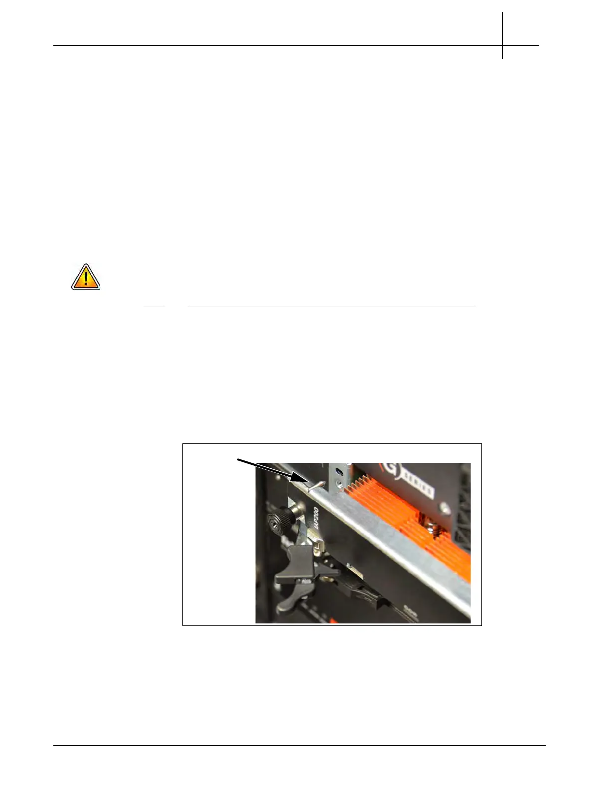
3. Guide the positioning pins of the blade un
til
they are inserted in the positioning
holes in the chassis (Figure 5.20).
Figure 5.20 - IAP Alignment
4. While squeezing the handle’s lever and latch together, close the left and right
ejec
tor handles until the inner sides of the ejector handles are attached to the
faceplate (Figure 5.21).
Tektronix Communications | For Licensed Users | Unauthorized Duplication and Distribution Prohibited

 Loading...