G10 Hardware Maintenance Guide 7.13.2 114
5
Maintenance Guidelines
Rev. 002-140228
6. Push the ejector handles inward until they are flush with the front of the chassis
and the blade is inserted fully (Figure 5.31).
Figure 5.31 - G10 IIC Ejector Handle - Seating the Board
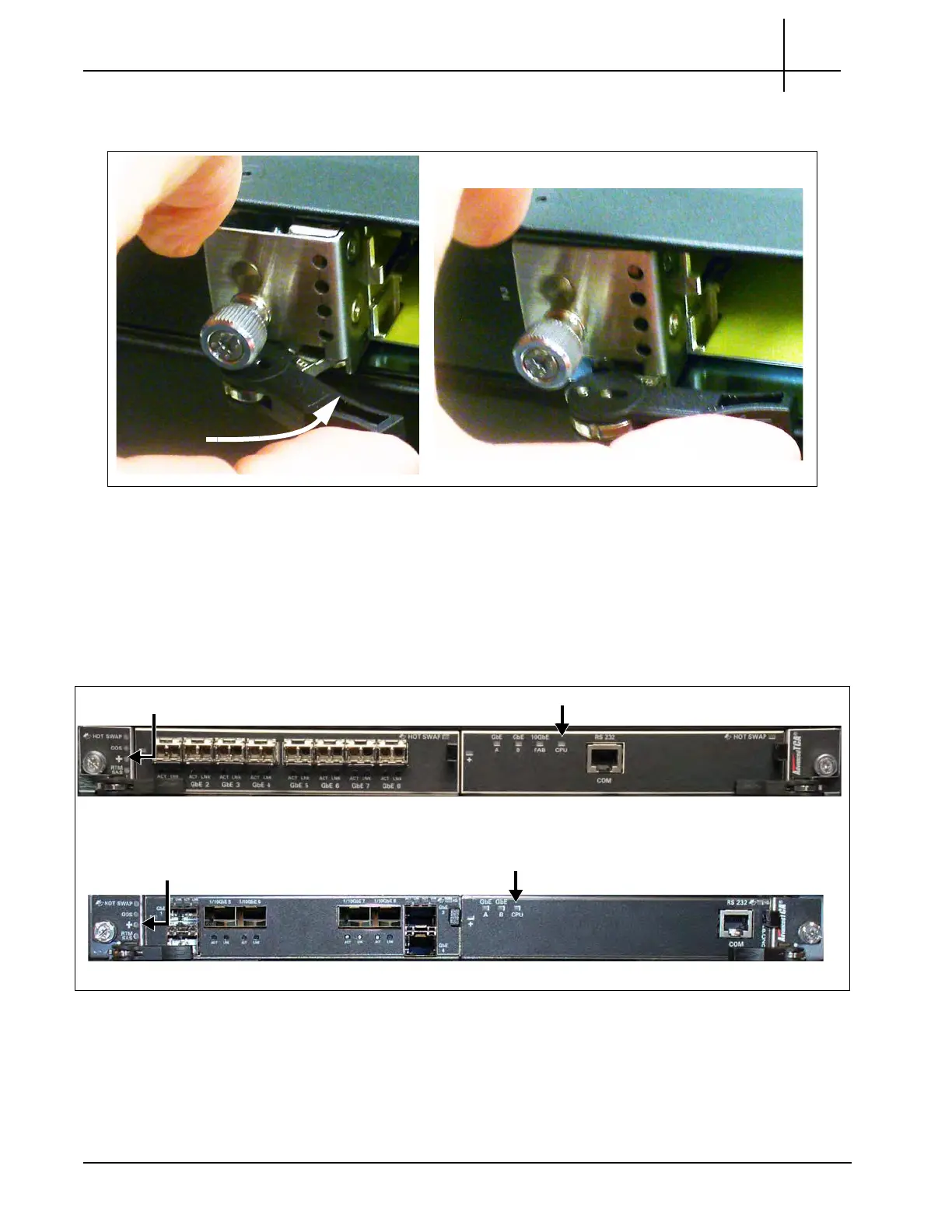
7. Verify the following LEDs on the front of the IIC (Figure 5.32):
The CPU LED is AMBER on the FPC100 AMC and GREEN on the
FPC200 AMC, indicating that the processor is functio
ning normally.
The + LED on IIC100 or IIC200 is GREEN, indicating that there are no
errors in overall health.
Figure 5.32 - G10 IIC100 and IIC200 LED Verification
FPC100 AMC CPU LED (Amber)
IIC100 + LED (Green)
IIC200
IIC100
IIC200 + LED (Green)
FPC200 AMC CPU LED (Green)
Tektronix Communications | For Licensed Users | Unauthorized Duplication and Distribution Prohibited

 Loading...