G10 Hardware Maintenance Guide 7.13.2 119
5
Maintenance Guidelines
Rev. 002-140228
7. Tighten the screws on the left and on the right of the card. The blue Hot Swap
LED blinks, indicating that the card is powering up.
8. Wait until the blue Hot Swap LED turns off, indicating that the board is activated.
9. Repeat Step 4 through Step 8 to insert the second 10G Interconnect Card.
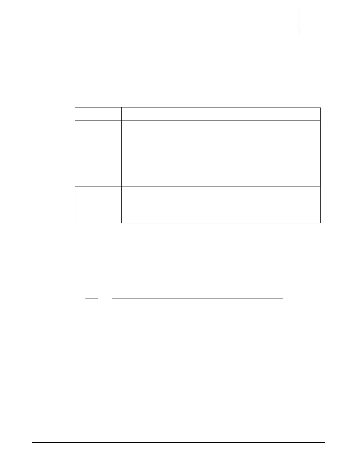
10. Perform the following actions, depending
on
the type of cable that you are
connecting:
11. Tektronix installs the DPC license and enables the DPC feature.
Removing the 10G Interconnect Card
The following procedure describes how to remove the card from a system if you need to
replace it. It assumes that the system is powered. If the system is not powered, you can
disregard the steps referencing the blue Hot Swap LED.
Step Action
1. Put on an ESD wrist strap or appropriate ESD grounding device.
2. Connect the strap to the shelf by attaching
it to the front or rear ESD jack /
ESD snap.
3. Remove the Ethernet cable (copper or multi-
mod
e fiber) that is attached to the
card. If removing fiber cable, also remove the SFP module to use in the
replacement card.
4. Unfasten the screws of the faceplate until the handle is detached from the front
p
ane
l of the card and the blue Hot Swap LED starts to blink.
5. Wait until the blue LED illuminates solid blue.
6. Remove the card from the shelf using the extraction handles.
7. Insert a replacement card; refer to Installing the 10G Interconnect Card.
Cable Type Instructions
Fiber
Verify that the SFP modules are inserted in the 10G interface cards.
Attach each end of the Ethernet cable to the SFP module in each
card, connecting the two cards. Be sure to connect the Tx in one card
to the Rx in the other card:
- Card 1 Tx connects to Card 2 Rx.
- Card 2 Tx connects to Card 1 Rx.
Copper
Verify that the SFP modules are NOT inserted in the 10G
interface cards.
Attach each end of the Direct Attach SFP+ copper cable directly into
the SFP socket in each card, connecting the two cards.
Tektronix Communications | For Licensed Users | Unauthorized Duplication and Distribution Prohibited

 Loading...