G10 Hardware Maintenance Guide 7.13.2 152
6
System Operating Specifications
Rev. 002-140228
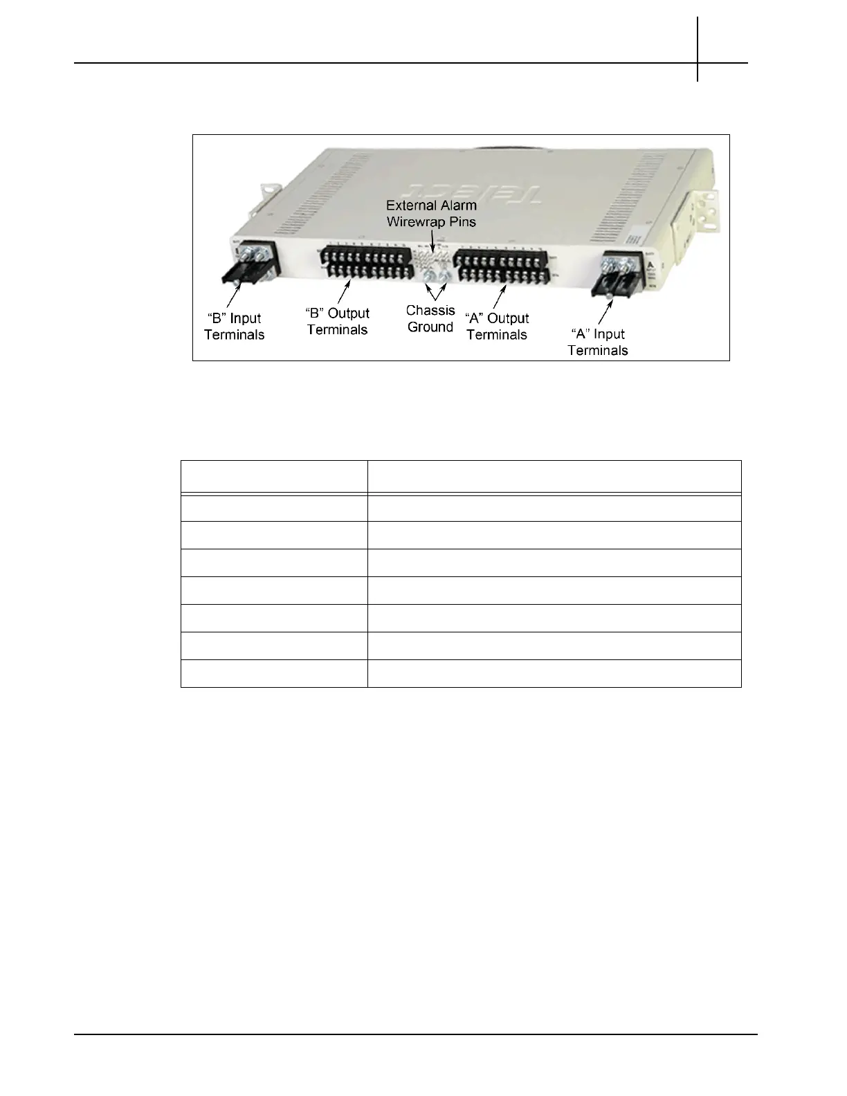
The back of the fuse panel provides input and output terminal connections, chassis ground
connections, and wirewrap pins for external alarm hookups (see Figure 6.3).
Figure 6.3 - Fuse Panel Rear View
Table 6.6 contains technical specifications for the fuse panel.
Table 6.6 - Fuse Panel Technical Specifications
Specification Panel Capacity
Panel capacity 20 fuses (dual groups of 10)
Current capacity 0.18 to 20 A per fuse, 100 A max per group (200 A total)
Input voltage 40 to –72 VDC
Alarm contact relays 2 A
Temperature -5 C to 55 C
Humidity 0 to 90%, non-condensing
Rack mounting Standard 19 inch rack, 1U high
Tektronix Communications | For Licensed Users | Unauthorized Duplication and Distribution Prohibited

 Loading...