G10 Hardware Maintenance Guide 7.13.2 20
1
G10 Probe Overview
Rev. 002-140228
The G10 Control Plane probe consists of two G10 chassis with the supported configurations
listed in Table 1.5. Refer to Figure 1.7 and Figure 1.8 for a graphical view of the control plane
probe configuration.
For details about the components of the control plane
probe, refer to the appropriate sections
in this guide. For information about installing and cabling the control plane probe, refer to the
G10 Control Plane Installation Guide.
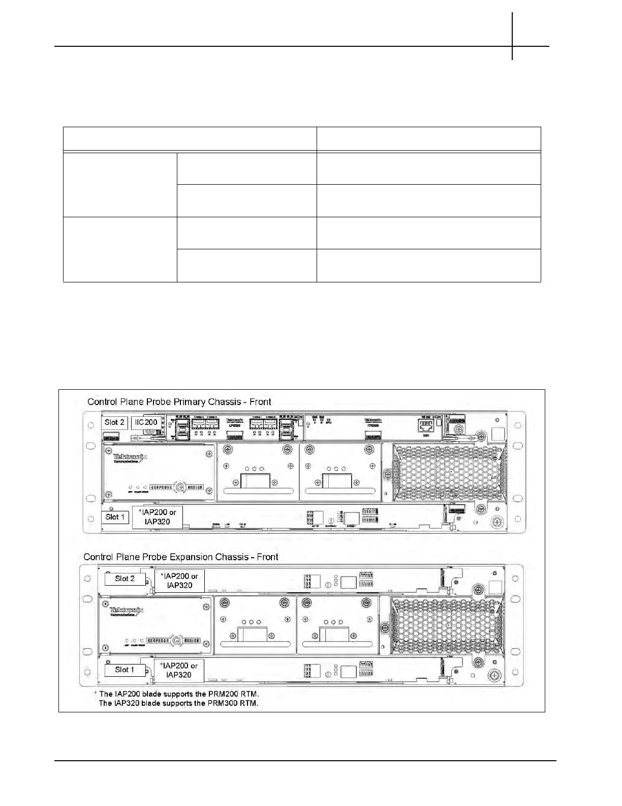
Figure 1.7 shows the front view of the G10 Control Plane probe components.
Figure 1.7 - G10 Control Plane Probe (Front)
Table 1.5 - G10 Control Plane
Pr
obe Configurations
Chassis Supported Blades
Primary Chassis Slot 1 (Bottom) IAP200 + PRM200 RTM OR
IAP320 + PRM300 RTM
Slot 2 (Top) IIC200 + SRM200 RTM OR
IIC100 + TRM100 RTM
a
Expansion Chassis Slot 1 (Bottom) IAP200 + PRM200 RTM OR
IAP320 + PRM300 RTM
Slot 2 (Top) IAP200 + PRM200 RTM OR
IAP320 + PRM300 RTM
a. The control plane probe only supports the IIC100/IAP200 configuration; the IIC100/IAP320
configuration is not supported.
Tektronix Communications | For Licensed Users | Unauthorized Duplication and Distribution Prohibited

 Loading...