G10 Hardware Maintenance Guide 7.13.2 33
3
Blades and RTMs
Rev. 002-140228
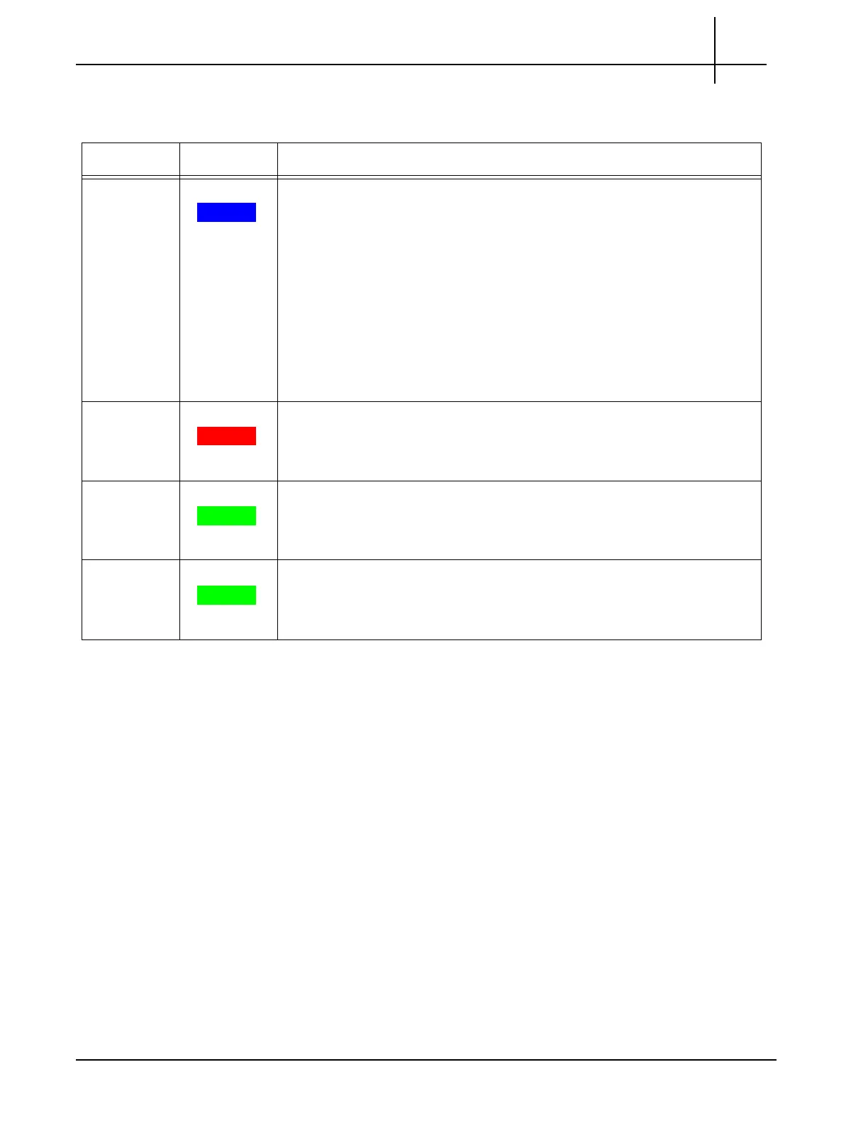
Table 3.1 describes the IIC LEDs.
Table 3.1 - IIC LEDs
LED LED Color Description
H/S BLUE Hot Swap Indicator which indicates when it
is safe to remove the module.
SOLID BLUE—The module is in standby mode and can be safely
extracted.
Off—The module is operational and it is unsafe to extract it.
BLINKING BLUE—The module is in transition between standby mode
and operational mode.
Note: When either AMC needs to be removed, you must power down and
remove the entire IIC
blade first.
Refer to Iris Interface Card (IIC100 or
IIC200) and LPC and FPC AMCs (IIC100 or IIC200) for removal/
replacement information.
OOS RED Indicates the device is out of service.
SOLID RED—The board is out of service.
OFF—No errors.
+ GREEN Indicates the health of the device.
SOLID GREEN—Out of Service.
OFF—No errors.
RTM SAS GREEN Green LED indicates status of the SAS RTM.
SOLID GREEN—No errors.
OFF—Fault condition.
Tektronix Communications | For Licensed Users | Unauthorized Duplication and Distribution Prohibited

 Loading...