G10 Hardware Maintenance Guide 7.13.2 36
3
Blades and RTMs
Rev. 002-140228
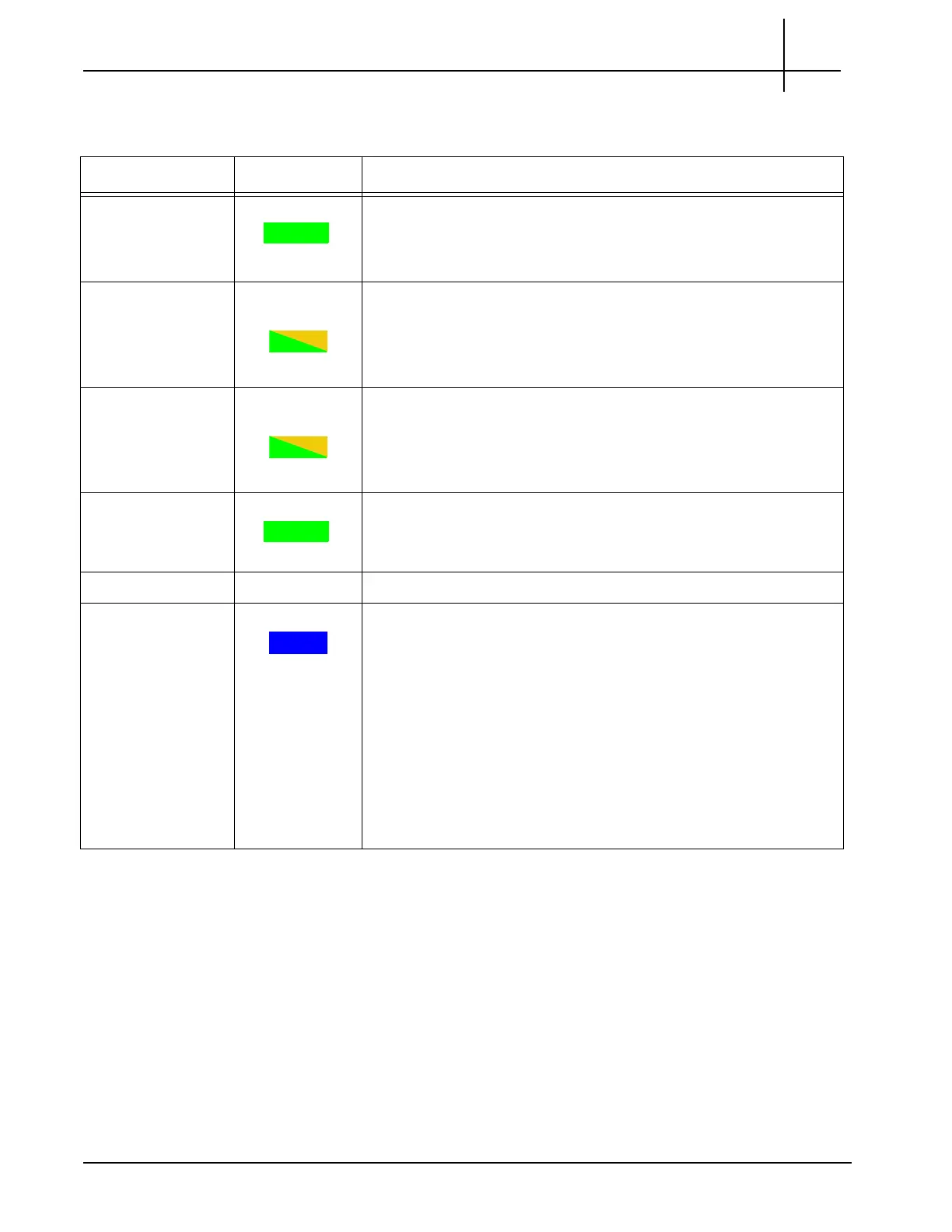
Table 3.2 displays the LED indicators of the FPC200 AMC.
Table 3.2 - FPC200 AMC LEDs
LED LED Color Description
+ GREEN
Indicates the health of the device.
SOLID GREEN—No errors.
OFF—Out of service.
GbE A GREEN or
AMBER
Indicates link status and activity for Gigabit Ethernet A connection
to carrier blade.
GREEN—The link is up.
BLINKING AMBER/GREEN—Link activity.
GbE B GREEN or
AMBER
Indicates link status and activity for Gigabit Ethernet B connection
to carrier blade.
GREEN—The link is up.
BLINKING AMBER/GREEN—Link activity.
CPU GREEN
Indicates health and status of the processor.
GREEN—The processor has normal functions.
RS 232 COM Not Used.
Hot Sw
ap BLUE
Hot Swap Indicator which indicates when it is safe to remove the
module.
SOLID BLUE—The module is in standby mode and can be
safely extracted.
OFF—The module is operational, and it is unsafe to extract it.
BLINKING BLUE—The module is in transition between standby
mode and operational mode.
Note: W
hen this board needs to be removed, you will be remov
ing
the entire IIC200. Refer to Iris Interface Card (IIC100 or IIC200) for
more information.
Tektronix Communications | For Licensed Users | Unauthorized Duplication and Distribution Prohibited

 Loading...