G10 Hardware Maintenance Guide 7.13.2 82
4
Storage Subsystem
Rev. 002-140228
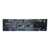
Table 4.4 displays the SA100R Controller Enclosure Rear Panel LEDs.
Table 4.4 - SA100R Controller Enclosure Rear Panel LEDs
LED Description
Power Supply Input
Source
This LED displays the color GREEN and indica
te
s whether the input source
power is good. Valid options are:
ON—The power is on, and input voltage is normal.
OFF—The power is off, or input voltage is below the minimum threshold.
Power Supply Fault This LED displays the color YELLOW and indicates the DC Voltage/Fan Fault/
Service
Required. Valid options are:
ON—The DC output voltage is out of range, or a fan is operating below the
minimum required RPM.
OFF—The DC output voltage is normal.
3 Gb SAS Activity
St
atus
These LEDs display the color GREEN. Valid options are:
BLINKING—The link has I/O activity.
OFF—The link is idle.
3 Gb SAS Link Status These LEDs display the color GREEN. Valid options are:
ON—The port is connected, and the link is up.
OFF—The port is empty, or the link is down.
OK to Remove This LED displays the color BLUE. Valid options are:
ON—The controller module can be removed.
OFF—The controller module is not prepared for removal.
Unit Locator This LED displays the color WHIT
E. Valid options are:
OFF—Normal operation.
BLINKING—Physically identifies the controller module.
FRU OK This LED displays the color GREEN. Valid options are:
ON—The controller module is operating normally.
OFF—The controller module is not OK.
BLINKING—The system is booting.
Fault/Service Required This LED displays the color AM
BER. Valid options are:
ON—A fault is detected or a service action is required.
BLINKING—A hardware-controlled power-up, cache flush, or restore error.
Ethernet LNK Status This LED displays the color GREEN. Valid options are:
ON—The Ethernet link is up.
OFF—The Ethernet port is not connected, or the link is down.
Tektronix Communications | For Licensed Users | Unauthorized Duplication and Distribution Prohibited

 Loading...