HYDROSTATIC POWER TRAIN
673831-Rev A 5-61
5
5. Loosen, but do not remove, the nut (6).
6. Loosen the wheel hub (7) from the motor shaft using
a puller.
7. Remove the nut (6) and wheel hub (7) from motor
shaft.
8. Remove key (8) from motor shaft.
9. Remove four screws (9) and lock washers (10).
10. Remove wheel motor (3) from motor mount (11).
Installation Notes
• Install the rear wheel motor by reversing the order of
removal.
• Apply anti-seize compound to the motor shaft
threads. Be careful not to apply anti-seize compound
to the motor shaft.
• Tighten nut (11) to 175–225 lb-ft
(237–305 N·m).
• Use a new cotter pin (5).
• Check hydraulic oil level. Add oil as needed. (Refer to
“Safety, Operation, and Maintenance Manual” for the
correct oil specifications.)
Shell Bearing Removal Tool
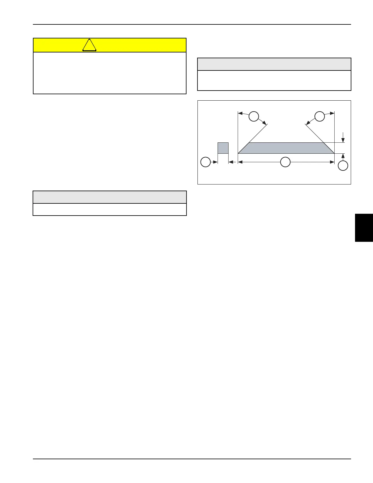
See Figure 5-68.
Figure 5-68: Shell Bearing—
Removal Tool
The wheel hub may move unexpectedly when
using a puller. To prevent injury and/or property
damage, do not remove the castle nut until the
wheel hub has been loosened from the wheel
motor shaft.
Required Materials
Anti-Seize Compound
Required Tools or Equipment
Shell Bearing—
Removal Tool
1 .25 in. (6.3 mm) 3 2.2 in. (55.9 mm)
2 .25 in. (6.3 mm) 4 45°
3
44
2
1

 Loading...

