5-62 673831-Rev A
HYDROSTATIC POWER TRAIN
5
Disassembly and Inspection
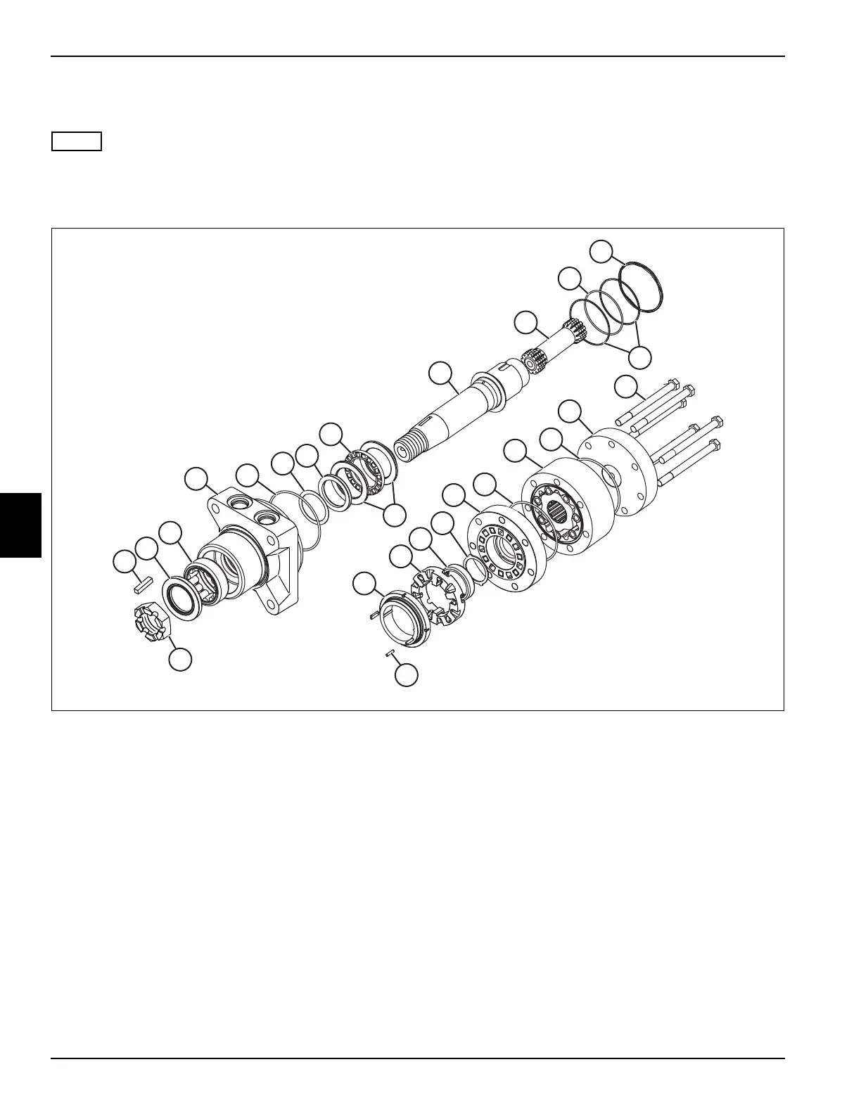
See Figures 5-69 through 5-71.
Disassembly is the same for both the 3WD and 4WD
motors. The difference between the motors is the width of
gerolor assembly (22) and length of the screws (24).
Figure 5-69
1. Place parts in assembly order on a clean work area
as they are removed.
2. Remove nut (1) and key (2) from output shaft.
3. Place motor housing (5) with screw end facing up.
4. Remove seven screws (24). Lift end cap (23) off
motor.
5. Remove and discard O-Ring (6).
6. Remove geroler (22) as an assembly. Do not
disassemble geroler.
7. Remove and discard O-Ring (6).
8. Remove valve plate (21). Do not remove bearing (19)
or thrust bearing (20) from valve plate.
9. Remove valve (18).
10. Remove balance ring (17). Dowel pins (16) were
glued to balance ring during assembly and may or
may not come loose.
11. Remove valve spring (15), back-up rings (13) and
O-Ring (14).
12. Remove drive (12).
13. Remove output shaft (11).
1 Nut 7 Back-up washer 13 Back-up Ring (2) 19 Bearing
2Key 8 Shaft Seal 14 O-Ring 20 Thrust Bearing
3 Grease Seal 9 Bearing Race (2) 15 Valve Spring 21 Valve Plate
4 Bearing Shell 10 Thrust Bearing 16 Dowel Pin (4) 22 Geroler Assembly
5 Housing 11 Output Shaft 17 Balance Ring 23 End Cap
6 O-Ring (3) 12 Drive 18 Valve 24 Screw (7)
1
2
3
4
5
6
6
6
7
8
9
10
11
12
13
14
15
16
17
18
19
20
21
22
23
24

 Loading...

