Chapter 7
126
UM10372_PCNC440_Manual_0221A
PROgRAMMiNg
7.3.19 Set Blended Path Control Mode – G64
To aempt to maintain the dened feed velocity, program: G64 P~ Q~
Word Definition
P~
If present, species the maximum acceptable tool path deviaon to round corners to maintain
speed. If P is omied then the speed is maintained however far from the programmed path the
tool cuts.
Q~
If present, species the maximum deviaon from collinearity that will collapse a series of linear G01
moves at the same feed rate into a single linear move.
NOTE: It is OK to program for the mode that is already acve.
7.3.20 Distance Mode – G90, G91
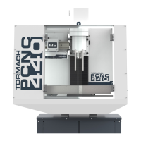
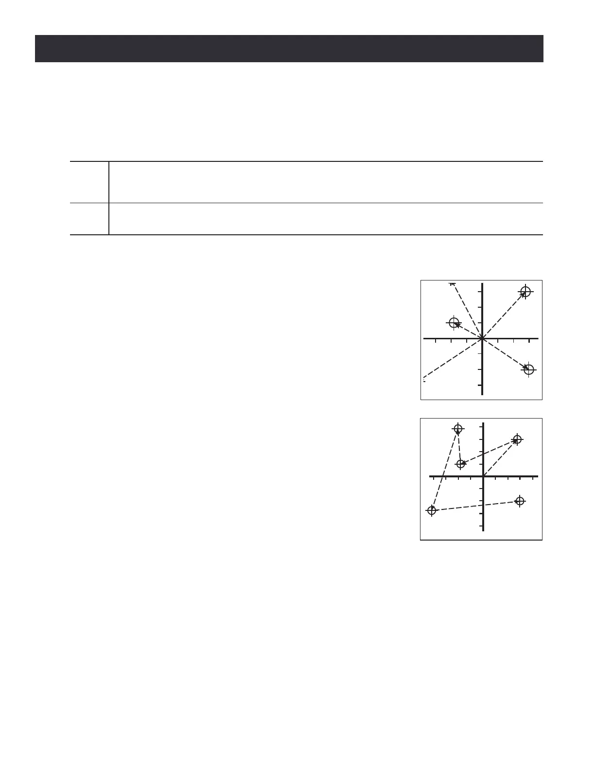
Interpretaon of the operang system-code can be in one of two distance
modes: absolute (see Figure 7.5) or incremental (see Figure 7.6).
To go into absolute distance mode, program: G90. In absolute distance
mode, axis numbers (X, Y, Z, A) usually represent posions in terms of
the currently acve coordinate system. Any excepons to that rule are
described explicitly in this secon.
To go into incremental distance mode, program: G91. In incremental
distance mode, axis numbers (X, Y, Z, A) usually represent increments
from the current values of the numbers. I and J numbers always
represent increments, regardless of the distance mode seng. K
numbers represent increments.
7.3.21 Arc Distance Mode – G90.1, G91.1
G90.1 – Absolute distance mode for I, and K osets. When G90.1 is in
eect I and K both must be specied with G02/3 for the XZ plane or it
is an error.
G91.1 – Incremental distance mode for I, and K osets. G91.1 Returns
I and K to their default behavior.
Figure 7.5
Figure 7.6