Chapter 5
47
UM10372_PCNC440_Manual_0221A
iNTRO TO PATHPilOT
5. Click the Zero Z buon next to the Z DRO to set the work oset Z to zero.
NOTE: This is just like typing 0.0 into the Z DRO and pressing Enter. To account for the thickness of the
paper used in touching o the work oset, you could type 0.003 in the Z DRO and press Enter.
Seng the X and Y Work Osets
Common posions for the X and Y part zeros are:
• The back le of the workpiece
• The center of the workpiece
• A feature (i.e., a hole or a boss) that already exists on the workpiece
For the rst part tutorial, we will use the X/Y center of the workpiece as the zero point. To set the X
and Y work osets for this part:
1. Using a straight edge, draw two lines on the 2” x 4” from corner to corner, creang an X in the
center of the workpiece.
2. Put the tool holder with the 3/8” end mill in it into the spindle.
3. Jog the mill so that the 3/8” end mill is approximately centered over the X on the workpiece.
4. Click the Zero X buon next to the X DRO.
5. Click the Zero Y buon next to the Y DRO.
5.1.7 Touch Off the Workpiece to Set Tool Length Offsets
This secon assumes that you have already set the work oset Z zero to the top surface of the
part using the steps in Seng Work Oset by Touching o Workpiece. The steps below describe
an alternave to using the TTS height gauge. If you have the 8” Digital Height Gauge (PN 31761), it
may be easier to measure the tools oine and enter their lengths directly into the tool table on the
Osets tab.
To touch o the tool osets:
1. The 3/8” tool used to set X and Y work
osets earlier in this chapter should
sll be in the spindle; this is Tool 1.
Type 1 in the tool DRO and click the
M6 G43 buon to tell the mill that
you have changed tools and want to
apply the tool length oset.
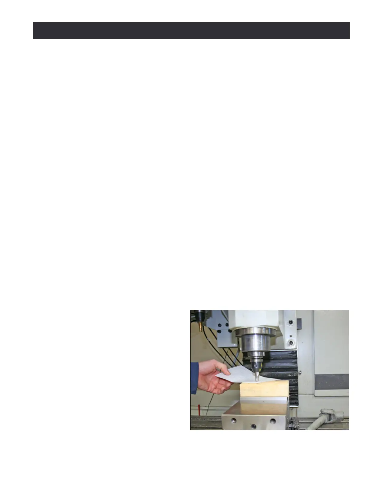
2. Jog the mill down so that the tool
just touches the top of the 2” x 4”
(see Figure 5.7).
Figure 5.7