Chapter 3
27
UM10372_PCNC440_Manual_0221A
iNSTAllATiON
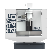
3.3.4 Attach Mill to Stand
WARNING! Crush Hazard: Keep hands
and body parts clear when lowering mill onto
stand. Failure to do so could result in death and/
or serious injury.
1. Place the oponal chip pan (PN 35673) on
top of oponal stand (PN 35671).
2. Lower mill slowly while lining up holes in
chip pan, mill, and stand (see Figure 3.5).
3. Using four M12 x 100 mm studs, washers,
and nuts, aach chip pan, mill, and stand
together; ghten nuts securely.
3.3.4.1 Non-Tormach Stands
If an alternave stand is used, ensure:
• Stand has a minimum weight capacity of
1000 lbs
• Mill is securely connected to stand
• Stand is stable and secure
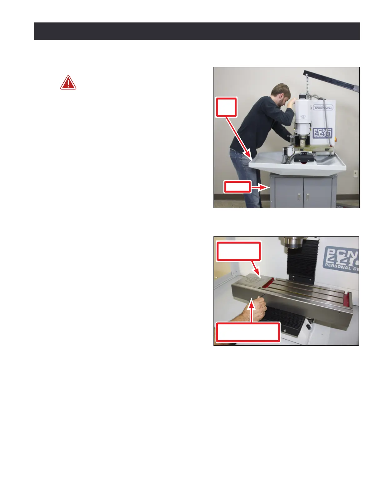
3.3.5 X-axis Motor Cover Plate
Install the X-axis Motor Cover Plate using
provided screws to aach it to le side of
machine table (see Figure 3.6).
3.3.6 X-axis Limit Switch Cover Plate
Install the X-axis Limit Switch Cover Plate using
provided screws to aach it to front of machine
table (see Figure 3.6).
3.3.7 Manual Oiler
Retract and release plunger unl oil moves through system. Aer that, pull plunger each me mill
is powered on and aer every four hours of operaon. For more informaon on providing oil to the
machine, refer to chapter 9, Maintenance.
3.3.8 Flood Coolant System
Fill the reservoir with pre-mixed coolant; refer to diluon instrucons for coolant product.
For informaon on installaon and use of the oponal Flood Coolant Kit (PN 35719), refer to
documentaon that ships with the product.
Figure 3.5
Chip
Pan
Stand
Figure 3.6
X-axis Motor
Cover Plate
X-axis Limit
Switch Cover Plate