Chapter 8
157
UM10372_PCNC440_Manual_0221A
ACCESSORiES
2. Refer to the following Probe Tip Adjustment screen instrucons:
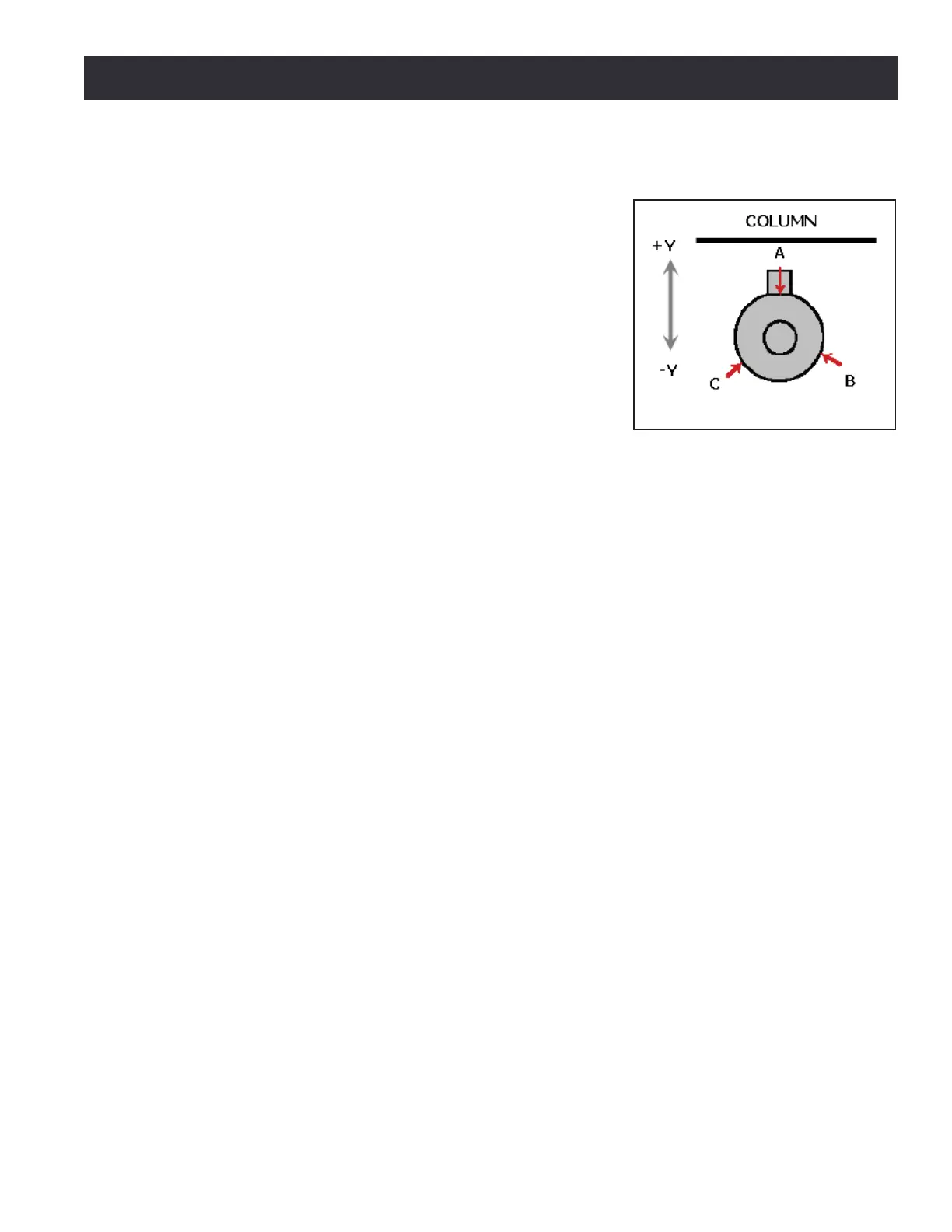
a. Orient the probe in the spindle so one of three
adjustment screws is opposite the machine column
(see Figure 8.10). Label this Screw A.
b. Press Y+ buon next to A.
c. Rotate spindle 120° clockwise (as viewed from above
the probe) so next screw is opposite machine column.
Press Y+ buon next to B.
d. Similarly, rotate spindle a third me unl nal screw
is opposite machine column. Press Y+ buon next to C.
e. Tighten the screw corresponding to the largest DRO
value (A, B, or C). Alternavely, if the screw cannot be
ghtened, loosen the other two screws.
f. Iterate this process unl all DROs read the same value. All screws should be ght.
Aer calibraon, mark the spindle pulley with a permanent marker or paint pen at a locaon that
corresponds to the angular posion of the probe cord. This allows the probe to be removed and
replaced in the exact spindle orientaon it was calibrated for – and eliminate error stackup.
8.3.5.2 Measuring Probe Tip Diameter
Use a micrometer to directly measure probe p diameter. Enter this data into tool table for Tool #99.
Figure 8.10