Chapter 4
38
UM10372_PCNC440_Manual_0221A
OPERATiON
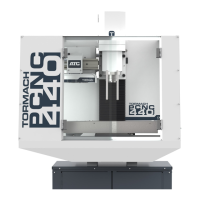
4.3.2 Jog Shuttle
The Jog Shule (PN 30616) is an oponal accessory (see Figure 4.4) that many operators nd
increases producvity, especially on short-run jobs requiring extensive seng up of the workpiece
and tooling.
The X, Y, Z and A buons are used to jog the X-, Y-, Z-, and A-axes, respecvely. An illuminated LED
light beside an axis DRO on the PathPilot interface indicates which axis is selected for jogging. The
Step buon on the Jog Shule cycles through the available jog step sizes. The acve size is indicated
by an illuminated LED light on the Step Size buons on the PathPilot interface (see Figure 4.5).
For more informaon on jogging methods, refer to chapter 6, PathPilot Interface.
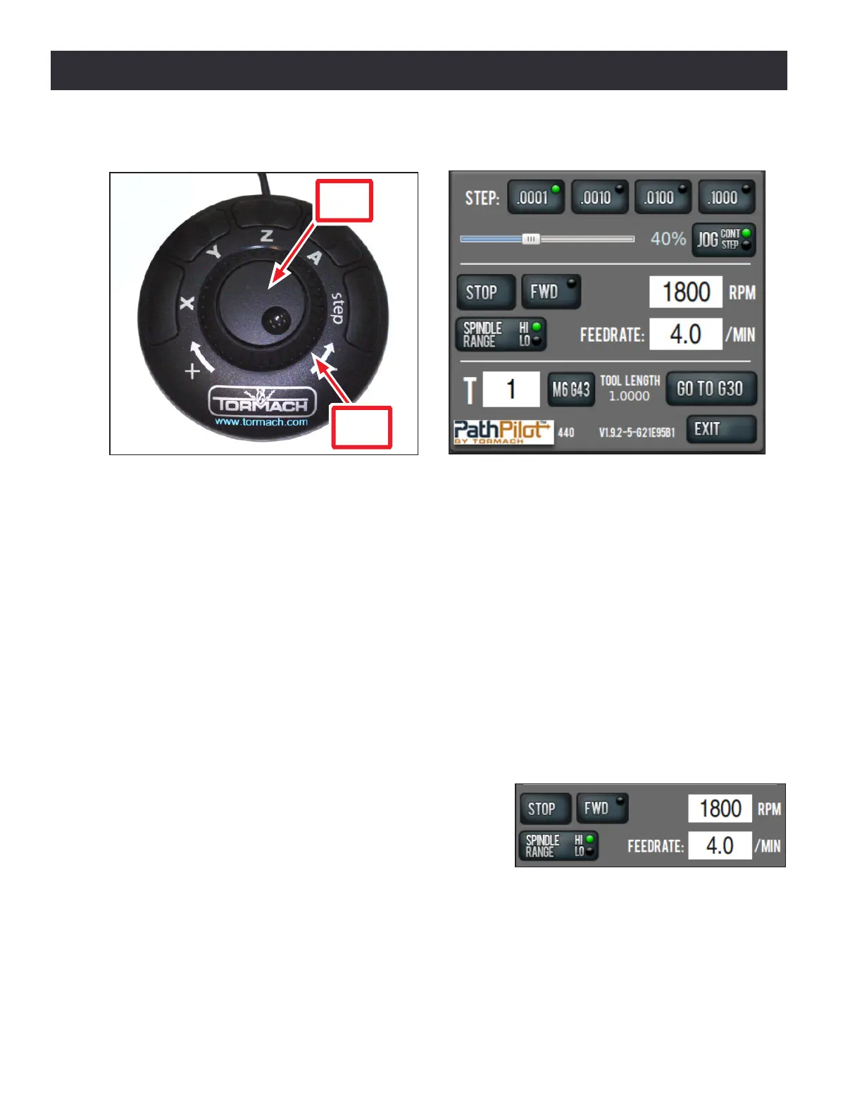
4.4 Spindle Controls
4.4.1 Spindle Control Via PathPilot Interface
Ensure the Spindle Range buon’s LED light (see Figure
4.6) correctly corresponds to the spindle belt posion,
either Hi or Lo; click to toggle between the two posions.
For more informaon on the procedure to change belt
posion, refer to Changing Spindle Speed Range secon
later in this chapter.
NOTE: A mismatch between the Spindle Range buon and actual spindle belt posion will result in the
commanded speed being dierent from the indicated RPMs.
Figure 4.4
Jog Shuttle
Jog
Wheel
Shuttle
Ring
Figure 4.5
Figure 4.6