Chapter 9
165
UM10372_PCNC440_Manual_0221A
MAiNTENANCE
The recommended method for gib adjustment is to measure axis lost moon while incrementally
ghtening the gibs to arrive at the correct seng. The following procedure describes this method
for the Z-axis. A similar procure can be used to adjust the X-axis and Y-axis gibs; however, it should
be noted that the X- and Y-axis gib adjustments cannot be considered in isolaon. Tightening or
loosening a gib on either axis also has an eect on the opposing axis.
1. Loosen upper gib screw eight rotaons and ghten the lower gib screw eight rotaons. This
ensures gib clearance is quite loose.
2. Use a dial indicator to measure lost moon in the Z-axis (for more informaon, refer to How to
Measure Lost Moon secon earlier in this chapter). With a very loose gib, the majority of the
measured lost moon is aributable to the backlash in the angular contact bearing pair. On
a new mill, this value measured should be less than 0.002” on the Z-axis and less than .0018”
on both the X- and Y-axis.
3. Tighten the gib by one turn
by loosening the lower
screw rst, then ghtening
the upper screw. Measure
the backlash again.
4. Repeat this procedure unl
the measured backlash
begins to increase. At this
point, the gib seng is
slightly too ght.
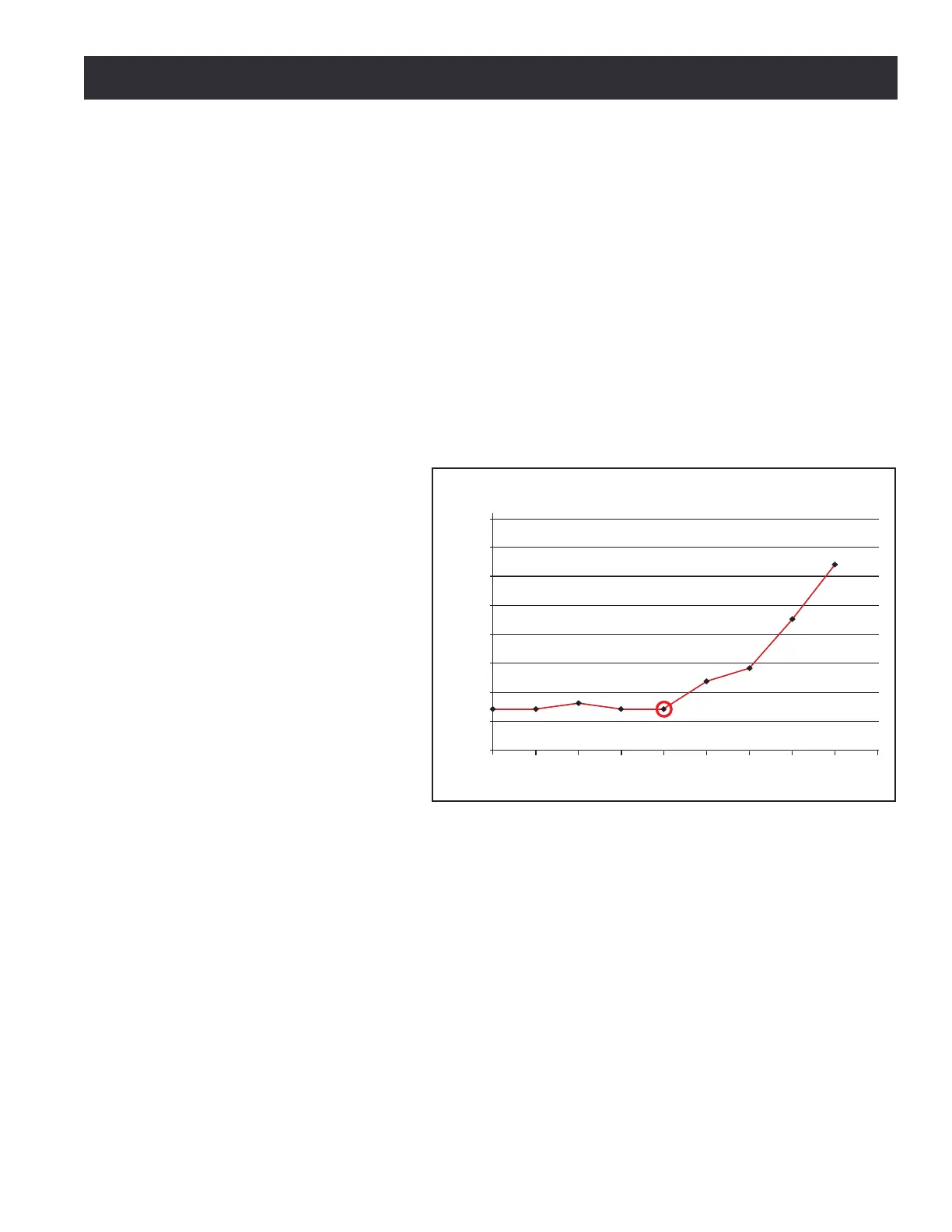
5. Back the adjustment o to
the point just before you
saw the increased backlash.
That is the ideal seng for
the axis (see Figure 9.3).
NOTE: Aer any gib adjustment, ensure
that both adjustment screws are ght or
the gib may move out of adjustment.
9.3.4 Angular Contact Bearing Preload Adjustment
9.3.4.1 Overview
Each axis ulizes a double-nut, pre-loaded ball screw. The preload in the ball nut is set at the factory
by placing a precision ground spacer between the two ball nuts. Lost moon aributable to the ball
screw assembly is 0.00”. Ball nut preload is not operator-adjustable.
The ball screw mount bearings are located in the stepper motor for each ball screw. These are a
pre-loaded angular contact bearing pair and are operator-adjustable. Under typical use, these
bearings should be adjusted so that observable lost moon is between 0.0012” to 0.0018”.
0.004
0.0035
0.003
0.0025
0.002
0.0015
0.001
0.0005
0
0 0.5 1 1.5 2 2.5 3 3.5 4 4.5
Backlash (in)
Backlash Versus Turns of Adjusting Screw
Number of Turns of Adjusting Screw
(0 represents a loose gib, 5 represents a tight gib)
Figure 9.3