Chapter 3
34
UM10372_PCNC440_Manual_0221A
iNSTAllATiON
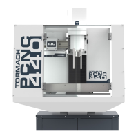
3.7.2 Verify Axis Function
1. Reference the mill by clicking the
Ref Z, Ref X, and Ref Y buons (see
Figure 3.19); the mill moves.
2. Next, switch to the Main screen.
3. Use keyboard to verify axis moon:
a. To move the X-axis, use the ←/→
arrow keys.
b. To move the Y-axis, use the ↑/↓
arrow keys.
c. To move the Z-axis, use the Page Up/Page Down keys.
4. To test the (oponal) jog shule:
a. Press the corresponding axis buon (X, Y, or Z) to select the axis.
b. Twist shule ring of jog shule to move axis; twist in opposite direcon to reverse direcon.
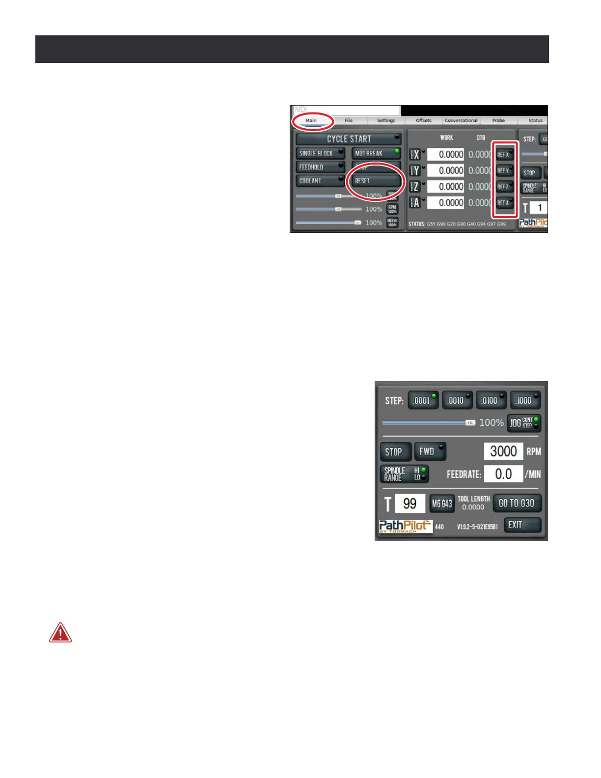
3.7.3 Verify Spindle Function
With the controller and mill powered on and the spindle
door closed, select the spindle range posion (high or low)
for the mill’s pulley belt on the PathPilot interface (see Figure
3.20). For more informaon, refer to chapter 4, Operaon.
Ensure the spindle is clear of any obstacles and set spindle
speed to 3000 RPM (see Figure 3.20).
Click the Fwd buon (see Figure 3.20) and the spindle
begins rotaon. Click the Stop buon and the spindle stops.
For more informaon on controlling the spindle, refer to
chapter 4, Operaon.
3.7.4 Installation Troubleshooting
Upon inial installaon, the most likely reason for non-funconing controls is wires that have
become loose during transport. Check to ensure all wires inside the electrical cabinet are properly
connected.
WARNING! Electrical Shock Hazard: Be sure to power o machine before making any electrical
modicaons. Failure to do so could result in death and/or serious injury.
1. Power o the mill according to the Power O/On Procedure detailed earlier in this chapter.
2. Using two ngers, rmly tug each wire connecon near its terminaon point. Any loose wires
should be re-seated and re-ghtened.
Figure 3.19
Figure 3.20