Chapter 3
33
UM10372_PCNC440_Manual_0221A
iNSTAllATiON
3.7 Validate Basic Installation
Validate basic setup before you install any
accessory kits.
IMPORTANT! Follow the Power O/On
Procedure detailed earlier in this chapter. Aer
powering on, jog the Z-axis up to remove the
shipping block between the spindle nose and the
machine table.
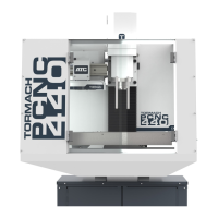
3.7.1 Verify Limit Switch Function
Limit switches prevent the mill from
exceeding its travel limits and provide a
reference locaon during the mill homing
procedure. There are three limit switches,
one for each axis of moon (X, Y, and Z),
as shown in Figure 3.17. If a limit switch
is triggered, the mill is placed in a reset
state. Verify funcon of the limit switches
as follows:
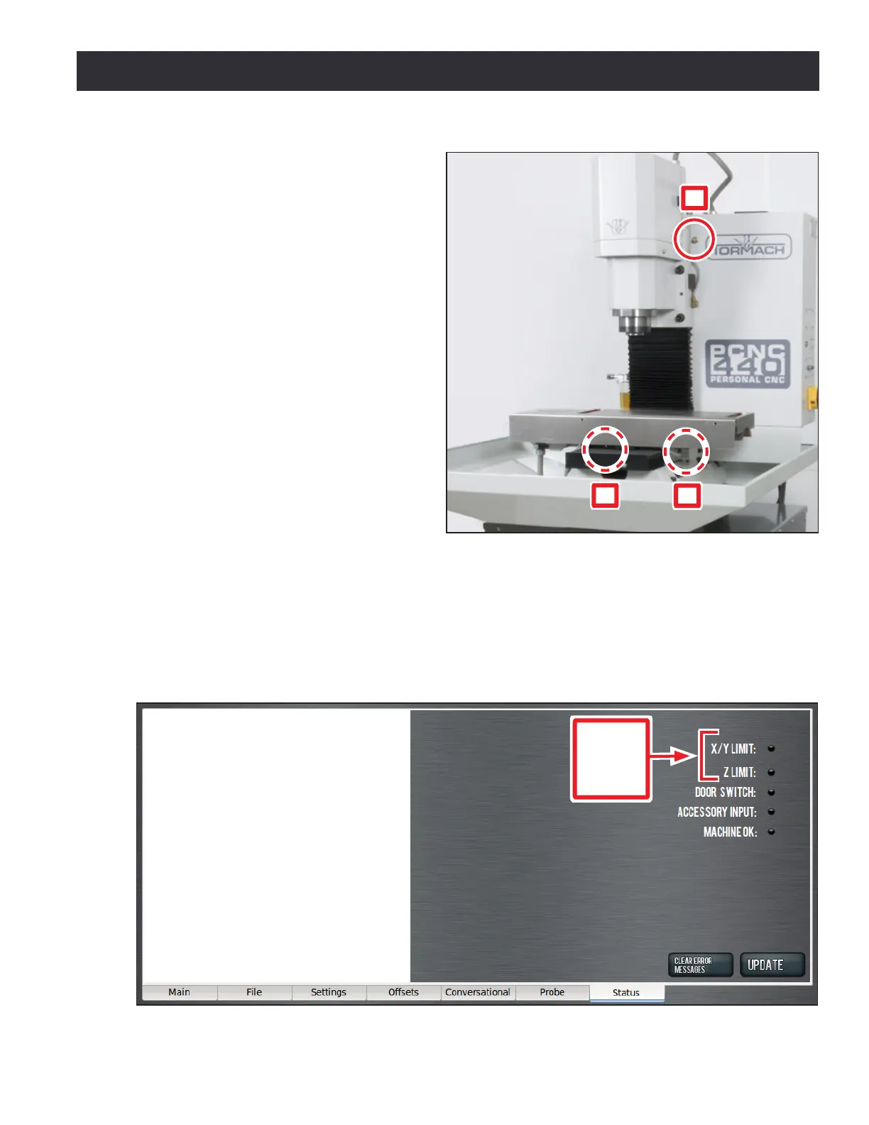
1. On the PathPilot interface, click the Status tab (see Figure 3.18).
2. Manually depress X, Y, and Z limit switches by hand (see Figure 3.17).
3. Verify that the corresponding LED light illuminates on the Status screen (see Figure 3.18).
4. Aer verifying limit switch funcon, click the ashing Reset buon.
Figure 3.18
Limit
Switch
LED
Lights
Figure 3.17
X
Y
Z