Chapter 3
26
UM10372_PCNC440_Manual_0221A
iNSTAllATiON
3.3.2 Remove Pallet Items
1. Carefully cut straps to remove plasc
Tool Box strapped to pallet (see
Figure 3.2); set aside for use later.
This box contains tools required for
installaon.
NOTE: The mill’s drawbar is located in the Tool
Box. For informaon on drawbar installaon,
refer to chapter 4, Operaon.
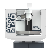
2. Remove X-axis Motor Cover Plate
and stainless steel X-axis Limit
Switch Cover Plate (see Figure 3.3);
set aside for installaon later.
IMPORTANT! Cut straps securing operator box
to pallet and keep together with mill for liing.
3.3.3 Lift and Move Mill
WARNING! Transport and Li Hazard:
The transport, liing, and moving of mill should
be done by qualied professionals. Failure to do
so could result in death, serious injury, and/or
mill damage.
3.3.3.1 Remove Mill from Pallet
The mill is secured to the shipping pallet
with four bolts/nuts. Before liing mill, use
16 mm wrench to remove nuts connecng
mill to pallet and discard.
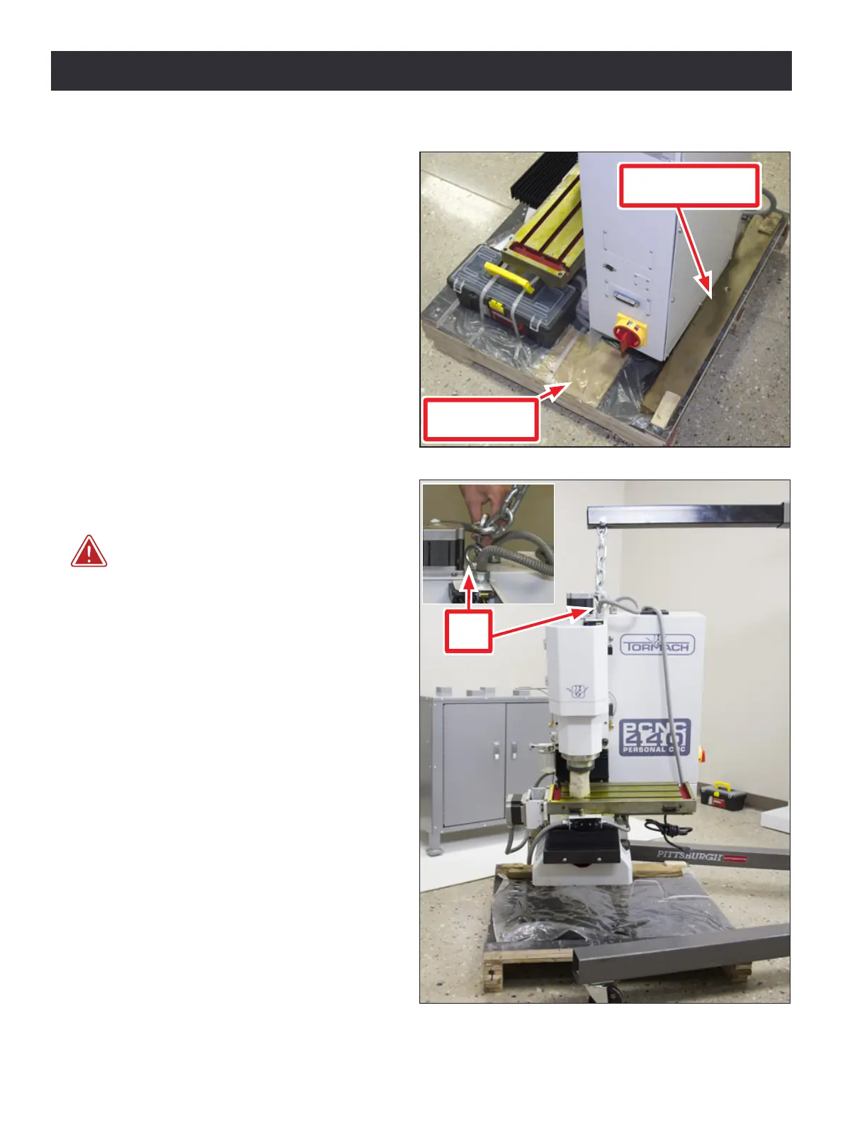
3.3.3.2 Lift Mill
Li the mill from above with either a
forkli or an engine hoist. The single Eye
Bolt on top of the column is suitable for
liing the enre weight of the mill (see
Figure 3.4 and inset). Do not aempt to li
mill from above using any other method.
If using an engine hoist, the minimum
distance between hoist legs is 22”, the
distance necessary to straddle the pallet.
Figure 3.3
X-axis Limit
Switch Cover Plate
X-axis Motor
Cover Plate
Figure 3.4
Eye
Bolt