Chapter 9
166
UM10372_PCNC440_Manual_0221A
MAiNTENANCE
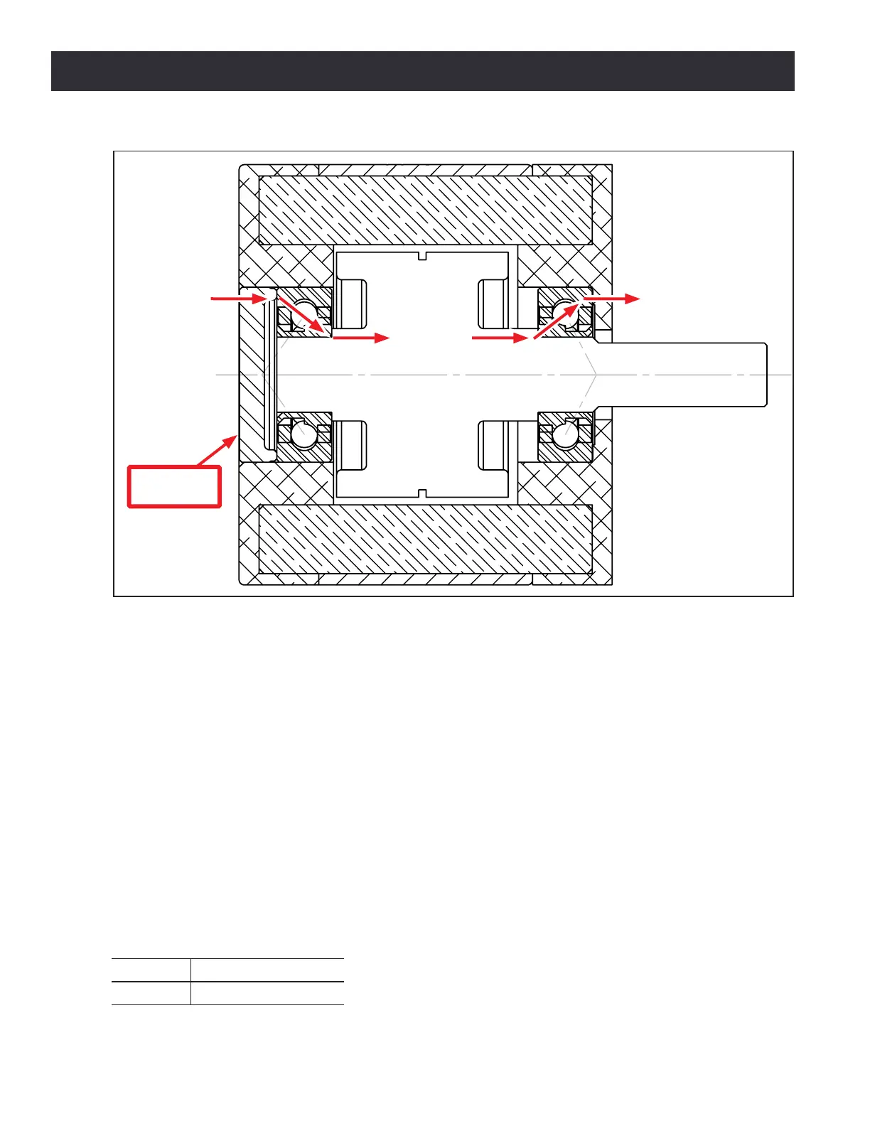
Figure 9.4 shows a cross secon of the stepper motor. There are two angular contact ball bearings,
forming a pre-loaded pair. The adjustment nut and stepper motor frame hold the two outer races
together.
The inner races are held between the sleeve (le side) and the shoulder cut into the ball screw sha
(right side). The sleeve is held against the le inner bearing race by the adjustment nut and a lock
nut. When the adjustment nut is screwed ghter toward the bearing pair, the preload increases.
Over me, it may become necessary to adjust the ball screw bearing preload to account for bearing
wear. Improper ball screw bearing preload will result in either excessive backlash in the mill if it is
too loose, or rapid wear and excessive fricon if it is too ght. It should be noted that if your ball
screw, ball nut, or angular contact bearings are worn, or if your gibs are adjusted too ght, you will
not achieve appropriate lost moon values.
9.3.4.2 Adjustment Procedure
To adjust the angular contact bearing pair preload, the following tool is required:
PN Descripon
32655 Pin Spanner Wrench
Figure 9.4
Adjustment
Nut