Chapter 9
163
UM10372_PCNC440_Manual_0221A
MAiNTENANCE
Tool ex, workpiece ex, xture ex, thermal expansion, and other factors contribute to the overall
machined-part accuracy.
The following tools are essenal:
• Dial indicator
• Dial test indicator
• Magnec dial stand
The following method describes the proper procedure to measure X-axis backlash. An analogous
procedure is used to measure Y- and Z-axis backlash.
1. Mount a dial indicator to the mill table along the X-axis to the le of the spindle, with the p
poinng at the spindle.
NOTE: If your indicator only reads in increments of .001”, then the best you can hope for a reading is
+/- .0005”. For best results, use an indicator that has increments less than .001”.
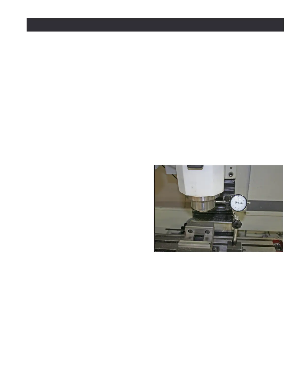
2. Jog the Y- and Z-axis to posion
the spindle head so the indictor p
contacts the outer diameter of the
spindle cartridge, as shown in Figure
9.1. It is best to use a at p on the
indicator as it will be contacng a
curved surface.
3. Carefully jog the X-axis in the
posive direcon unl the indictor
contacts the spindle. Aer inial
contact, connue jogging the X-axis
in the posive direcon so that the
dial makes at least one complete
revoluon and stop jogging when
the dial reads 0.
4. Zero the X DRO on PathPilot® interface.
5. In the MDI eld, program a posive X move of .01” at a feed rate of 5 IPM: G01 X.01 F5. The
spindle head moves slightly in the +X direcon. When nished, the indictor should read .010”.
6. Program an X move back to 0: G01 X0 F5. The spindle head moves slightly in the -X direcon.
The X DRO should say 0; however, the dial indicator should read a number very close to 0. This
value is the measured lost moon.
Figure 9.1


 To Next Page