Chapter 3
29
UM10372_PCNC440_Manual_0221A
iNSTAllATiON
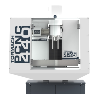
3. Aach the 4-port USB hub (provided
in the machine owner’s kit) below
the Brix PathPilot Controller with
double-sided tape (provided with
the controller mount).
4. Connect the USB hub’s cord to any
open USB port on the Brix PathPilot
Controller.
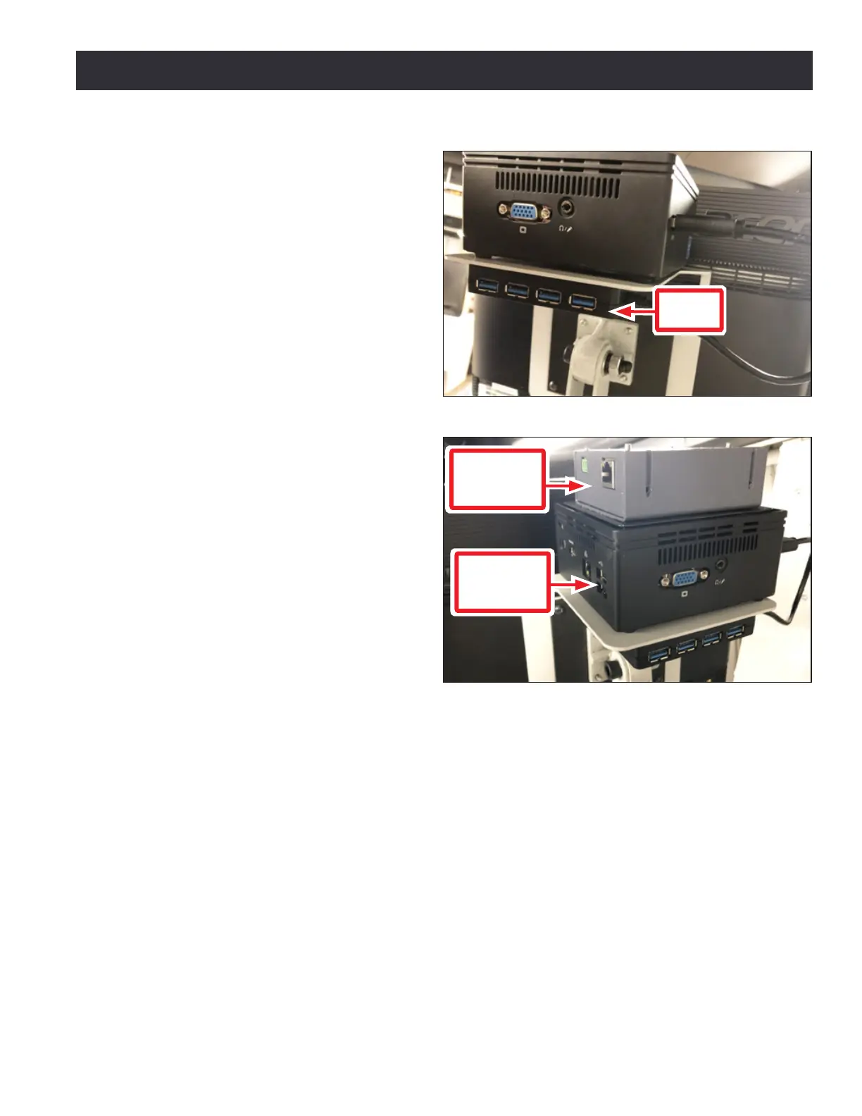
5. Find the PathPilot Controller for 15L
Lathe and PCNC Mills (PN 50848)
provided. Then, remove the lm
from the double-sided tape on the
boom of the case.
6. Put the case on top of the Brix
PathPilot Controller. Press down
rmly to aach it in place.
7. Connect all USB accessories to the
USB hub:
• Jog Shule (PN 30616)
• Keyboard
• Mouse
• Monitor
8. Connect the monitor’s video cable
to the Brix PathPilot Controller.
9. Route the loose end of the video cable toward the monitor, and then connect it to the monitor.
10. Connect the power supply to the Brix PathPilot Controller.
11. Route the loose end of the power cords (from the USB hub and both PathPilot controller
units) to a power strip, and then connect them.
12. Connect the DB-25 interface cable into the DB-25 outlet on the side of the electrical cabinet.
13. Route the loose end of the DB-25 interface cable to the PathPilot Controller for 15L Lathe and
PCNC Mills, and then connect it to the mill interface port.
14. Find the Ethernet cable and connect it to the Ethernet outlet on the PathPilot Controller for
15L Lathe and PCNC Mills.
15. Route the loose end of the Ethernet cable toward the Brix PathPilot Controller, and then
connect it to the Brix PathPilot Controller.
16. Secure the wire loom, Ethernet cable, and power supply cables to the Controller Arm with six
wire e mounts and six cable es.
Figure 3.10
USB
Hub
Figure 3.11
PathPilot
Controller
for 15L/440
Brix
PathPilot
Controller